Punching machine with high vibration resisting capacity

A punching machine and capability technology, applied in the field of punching machines, can solve problems such as difficulty in blanking, device damage, ground damage, etc., and achieve the effects of preventing dangerous accidents, reducing impact force, and improving practicability

Inactive Publication Date: 2017-10-24
朱发平
View PDF2 Cites 10 Cited by
  • Summary
  • Abstract
  • Description
  • Claims
  • Application Information

AI Technical Summary

Problems solved by technology

[0003] With the continuous development of science and technology, the stamping machine technology is also constantly improving, but there are still many defects in modern stamping machines. The material will be very difficult, and manual cutting may sometimes cause dangerous situations. At the same time, when the modern stamping machine is working, it will produce a very strong vertical impact force due to the impact of the stamping cylinder. The large impact force will not only affect the device itself. damage, and will cause greater damage to the ground

Method used


Image

  • Punching machine with high vibration resisting capacity
  • Punching machine with high vibration resisting capacity

Examples


Embodiment Construction

[0016] The technical solution of this patent will be further described in detail below in conjunction with specific embodiments.

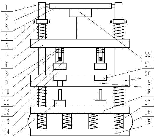
[0017] see Figure 1-2 , a stamping machine with strong shock resistance, comprising a lower base plate 15, an upper base plate 18, a support plate 20, a sliding plate 7 and a column 1, the upper end of the lower base plate 15 is provided with an upper base plate 18, the lower base plate 15 and the upper base plate 18 Airbags 16 are arranged between them, and a plurality of spring columns 17 are arranged in the airbags 16; four uprights 1 are fixedly connected to the four corners of the upper end of the upper bottom plate 18, and the uprights 1 are sequentially provided with supporting plates 20 and sliding plates from bottom to top 7. Between the upper base plate 18 and the support plate 20, a first damping spring 13 is set on the column 1, and a plurality of ejection cylinders 14 are fixedly installed on the upper end of the upper base plate 18, ...


PUM


Abstract

The invention discloses a punching machine with high vibration resisting capacity. The punching machine comprises a lower baseplate; an upper baseplate is arranged at the upper end of the lower baseplate; four stand columns are fixedly connected to four corners of the upper end of the upper baseplate; the stand columns are sleeved with a support plate and a slide plate in sequence from bottom to top; a first vibration reducing spring is sleeved on the stand columns between the upper baseplate and the support plate; multiple ejection cylinders are fixedly mounted at the upper end of the upper baseplate; multiple concave molds are arranged on the upper surface of the support plate; multiple fixed rods are fixedly connected to the lower end of the slide plate; a fixed sleeve is arranged on the outer sides of the fixed rods; the outer side of the lower end of the fixed sleeve is fixedly connected with a convex mold; a lantern ring is sleeved on the stand columns above the slide plate; and a second vibration reducing spring is sleeved on the stand columns between the lantern ring and the slide plate. The punching machine is simple in structure and reasonable in design, can greatly reduce vibration generated during working, and prolongs the service life.

Description

technical field [0001] The invention relates to a stamping machine, in particular to a stamping machine with strong shock resistance. Background technique [0002] The stamping machine drives the flywheel through the motor, and through the clutch, the transmission gear drives the crank linkage mechanism to move the slider up and down, and drives the drawing die to form the workpiece. The stamping machine has an important application in forging and shaping. [0003] With the continuous development of science and technology, the stamping machine technology is also constantly improving, but there are still many defects in modern stamping machines. The material will be very difficult, and manual cutting may sometimes cause dangerous situations. At the same time, when the modern stamping machine is working, it will produce a very strong vertical impact force due to the impact of the stamping cylinder. The large impact force will not only affect the device itself. Damage will occ...

Claims


Application Information

Patent Timeline
Patent Type & Authority Applications(China)
IPC IPC(8): B30B15/00
CPCB30B15/0076
Inventor 朱发平
Owner 朱发平
Why Eureka
Try Eureka