
Mechanical arm

A robotic arm and drive control technology, applied in the field of bionic robotic arms, can solve the problems of difficult control, unstable operation of the device, unsuitable for anthropomorphic use, etc., and achieves the effect of reducing costs and facilitating control

Pending Publication Date: 2017-10-24
SHANGHAI LINGXIAN ROBOTICS TECH CO LTD
View PDF11 Cites 8 Cited by
  • Summary
  • Abstract
  • Description
  • Claims
  • Application Information

AI Technical Summary

Problems solved by technology

However, the control of the traditional parallel robot is difficult, and it is easy to generate coupled translational motion, so it is not suitable for direct application to the state of anthropomorphic use (such as the arm of a humanoid robot to grab objects, work with people, etc.)
[0004] Therefore, those skilled in the art are committed to developing a new type of mechanical arm, which overcomes the shortcomings of the traditional serial mechanical arm with a center of gravity forward and unstable operation of the device, while reducing the load moment at the joints and saving costs. The method causes coupling translation and limits its applicable environment

Method used


Image

  • Mechanical arm
  • Mechanical arm

Examples


Embodiment 1

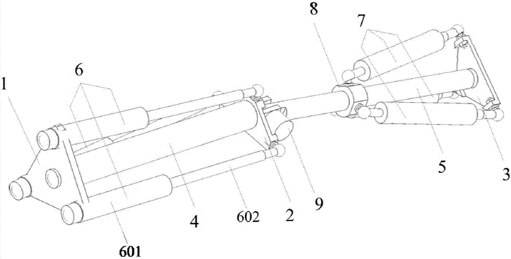
[0033] Such as figure 1 As shown, this embodiment provides a mechanical arm structure imitating the design of the human arm, including three independent joints designed according to the movement of the human arm, including shoulder, elbow, and wrist, wherein the position of the first platform 1 is the shoulder joint, imitating the human arm The shoulder design has three independent degrees of freedom of rotation; the position of the second platform 2 is the elbow joint, which can rotate around the only central rotation axis, including an independent degree of freedom; the position of the third platform 3 is the wrist joint, Like the shoulder joint, it has three independent degrees of freedom of rotation. The robotic arm as a whole includes 7 independent degrees of freedom, which is flexible and efficient, and has excellent bionic motion effects.

[0034] 1.1 Shoulder joint:

[0035] In the robotic arm provided in this embodiment, the movement of the shoulder joint is compose...

Embodiment 2

[0054] This embodiment provides a simplified form of the mechanical arm in Embodiment 1, its structure is as follows figure 2 shown. Wherein, the third platform 3 of the wrist is connected to the second arm 5 through a ball joint, and the third platform 3 can rotate around the ball joint at the joint. The third platform 3 is connected with two sets of second driving control parts 7 through a ball joint. The mechanical arm provided in this embodiment can jointly determine the spatial pose of the third platform 3 of the wrist through the length changes of the two sets of second driving control parts 7 , and the rotation of the third platform 3 has two degrees of freedom.

[0055] In other preferred embodiments of the present invention, the driving control parts of the wrist and the shoulder are hydraulic cylinders, wherein the translation part is a hydraulic cylinder piston, and the driving part is a cylinder body of the hydraulic cylinder. There is hydraulic oil in the cylin...


PUM


Abstract

The invention provides a novel biomimetic mechanical arm structure. According to the mechanical arm, the drawbacks are overcome that the gravity center of a traditional series mechanical arm is in the front and a device is low in stiffness. A parallel drive mode is utilized to move the gravity center backwards, therefore in the premise that the working load is constant, the load of each joint is reduced, the load of a drive device is reduced, and the cost is saved. At the same time, the joints can only swing and do not introduce coupling translation like the majority of traditional parallel mechanisms. The mechanical arm adopts biomimetic design and comprises two connecting rods swinging in space. A linear drive part is utilized to achieve three degrees of freedom motion independently swinging on the shoulder and the wrist. A rotary drive unit is utilized to achieve one degree of freedom swing at the elbow. The motion mode of the mechanical arm is similar to that of the human arm, and the mechanical arm has an excellent biomimetic motion effect.

Description

technical field [0001] The invention relates to the field of robotic automatic processing, in particular to a novel bionic mechanical arm. Background technique [0002] A robotic arm is an arm-like structure designed to achieve specific spatial motion. [0003] At present, common robotic arms contain 6 or 7 degrees of freedom, each of which is driven by a driving component to move to a specific position, and each degree of freedom is connected in series. In this type of structure, the mass is concentrated at the end of the rod, which in turn increases the load moment on the next-level joint. However, the traditional parallel robot is difficult to control, and it is easy to generate coupled translational motion, so it is not suitable for direct application to anthropomorphic use (such as humanoid robot arms to grab objects, work with people, etc.). [0004] Therefore, those skilled in the art are committed to developing a new type of mechanical arm, which overcomes the shor...

Claims


Application Information

Patent Timeline
Patent Type & Authority Applications(China)
IPC IPC(8): B25J9/00B25J9/10B25J18/00
CPCB25J9/0009B25J9/10B25J18/00
Inventor 张戬杰
Owner SHANGHAI LINGXIAN ROBOTICS TECH CO LTD
Learn More