
Micro electrical discharge pulse power source and segmental control method based on micro electrical discharge pulse power source

A pulsed power supply and electric spark technology, applied in control/regulation systems, circuits, manufacturing tools, etc., can solve the problems of low switching control accuracy and slowness, complex structure, etc., to ensure the multi-signal logic processing capability and driving speed, and simplify the circuit. Topology, the effect of improving processing efficiency

Active Publication Date: 2017-10-20
NANJING UNIV OF SCI & TECH
View PDF7 Cites 28 Cited by
  • Summary
  • Abstract
  • Description
  • Claims
  • Application Information

AI Technical Summary

Problems solved by technology

This composite structure requires two sets of power loops, the structure is complex, and there are also problems with the response speed of the detection circuit and the controller, and the switching control accuracy is not high or slow.

Method used


Image

  • Micro electrical discharge pulse power source and segmental control method based on micro electrical discharge pulse power source
  • Micro electrical discharge pulse power source and segmental control method based on micro electrical discharge pulse power source
  • Micro electrical discharge pulse power source and segmental control method based on micro electrical discharge pulse power source

Examples


specific Embodiment approach

[0045] Based on the novel electric spark pulse power supply provided by the present invention, the specific implementation of the segmental control method for gap voltage and gap current provided by the present invention is as follows:

[0046] The schematic diagram of each stage in a processing cycle in the new micro-EDM pulse power source processing is as follows: Figure 7 As shown, a processing cycle includes the processing stage and the deionization stage, and the processing stage includes the arc ignition stage and the discharge stage. A processing cycle 0~t 3 In the time period, the time t when the deionization phase starts 2 and the time t at the end of a processing cycle 3 They are all set, the transition time t between the arc ignition stage and the discharge stage 1 It is the moment when the gap is broken down, and it is constantly changing due to the influence of the state and properties of the gap. In the arc ignition stage, the gap has not been broken down, th...


PUM


Abstract

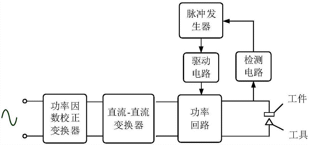
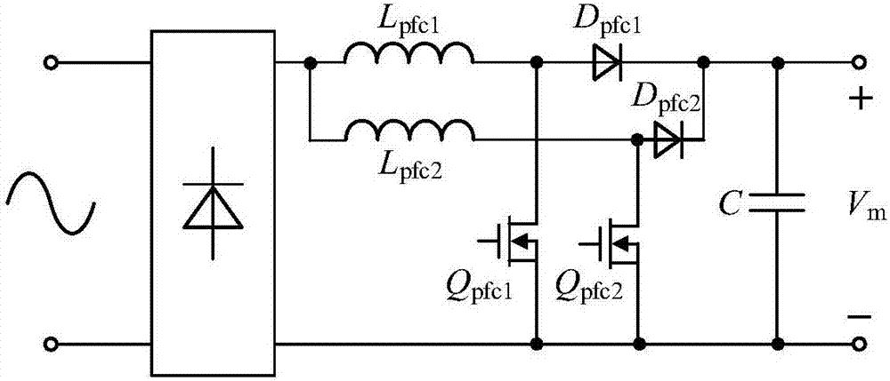
The invention discloses a micro electrical discharge pulse power source. The micro electrical discharge pulse power source comprises a power factor correction converter, a DC-DC converter, a power loop, a driving circuit, a pulse generator and a detection circuit, wherein the power loop comprises 6 switch tubes Qp, Q1, Q2, Q3, Q4 and Qoff and one inductor Llimit, the four switch tubes Q1-Q4 are connected in a bridge structure, the switch tube Qp is connected with an output side of the DC-DC converter and an input side of a full-bridge converter, after the switch tube Qoff is in parallel connection with a gap, one end of the switch tube Qoff is connected with a center point of a bridge arm through the inductor Llimit, and the other end is directly connected with a center point of another bridge arm. The invention further comprises a segmental control method based on the micro electrical discharge pulse power source. The micro electrical discharge pulse power source is advantaged in that only one power loop is comprised, the structure is simple, the volume is small, switching of voltage control and current control is carried out in a set of power loop through the corresponding segmental control method, voltage control and current control are mutually independent, and fast switching and precise and stable control can be realized.

Description

technical field [0001] The invention belongs to the field of pulse power supply for electric discharge machining, in particular to a micro electric discharge pulse power supply and a segmented control method based on the power supply. Background technique [0002] Continuous positive and negative polarity processing can improve the quality of processing, and has a certain effect on the shaping of discharge pits. In order to meet the requirements of various processing occasions and processing conditions, the EDM pulse power supply must have the ability of positive and negative polarity processing. In order to achieve positive and negative polarity machining, the existing EDM pulse power supply uses a full-bridge converter as the main topology of the power loop, and one or more current-limiting resistors are required in the power loop. Due to the existence of the current-limiting resistor, the processing efficiency of the pulse power supply is not high, and it cannot meet the...

Claims


Application Information

Patent Timeline
Patent Type & Authority Applications(China)
IPC IPC(8): H02M3/156B23H1/02
CPCB23H1/02H02M3/156
Inventor 杨飞华晗杨蛟李春晖曹勇彭富明
Owner NANJING UNIV OF SCI & TECH
Learn More