
Asymmetric half-bridge flyback drive circuit

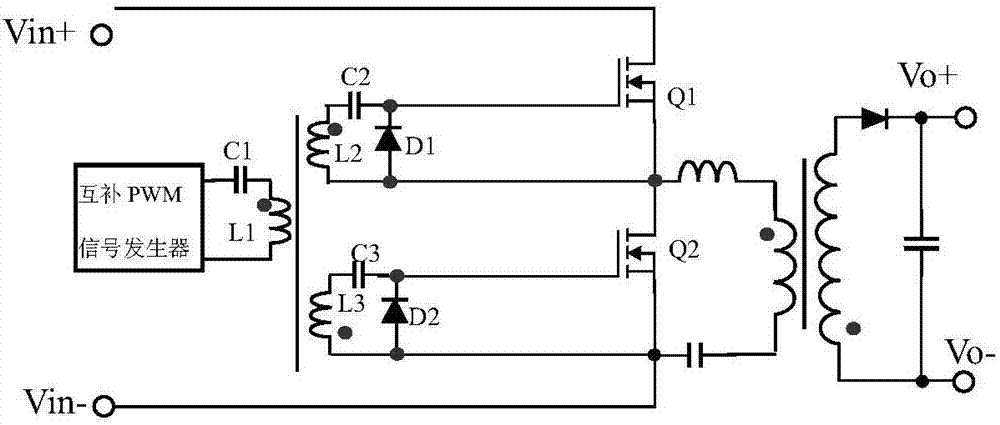
A driving circuit, asymmetric technology, applied in the direction of electrical components, adjusting electrical variables, high-efficiency power electronic conversion, etc., can solve the problems of difficult control of dead time, poor consistency of driving signals, and affecting the quality of driving waveforms, etc., to achieve working timing The effects of high consistency, improved driver consistency, and high timing consistency

Pending Publication Date: 2017-10-20
MORNSUN GUANGZHOU SCI & TECH
View PDF4 Cites 3 Cited by
  • Summary
  • Abstract
  • Description
  • Claims
  • Application Information

AI Technical Summary

Problems solved by technology

[0006] Therefore, in order to meet the above requirements and overcome the shortcomings in the above circuits, the method of series mode of the asymmetrical half-bridge flyback circuit is produced. By connecting the primary side in series, the secondary side adopts the transformer coupling method to solve the problem caused by the wide-range high-voltage input. However, for high-voltage input, in the case of a wide range of input voltage, in order to meet the effective voltage equalization of the input bus capacitor, the driving signal requires a small level voltage change and high timing consistency. Therefore, the switching tube drive in the asymmetrical half-bridge flyback circuit in series mode will become more complicated; most of the existing driving methods are optocoupler drive or isolation drive, and ordinary optocoupler is difficult to meet the requirements, although there are High-speed drive optocouplers are available, but their higher prices will also lead to an increase in power supply costs. At the same time, this high-speed optocoupler needs an isolated power supply to supply power to the optocoupler, which in turn leads to an increase in power supply costs. At the same time, as the power supply itself It is also a kind of contradiction; the existing drive usually adopts a magnetic isolation drive method, but under the condition of multiple sets of drive signals, the coupling between the windings is poor, the consistency of the drive signals is poor, and the dead time is not easy to control. It may even cause the drive to work abnormally; at the same time, with the increase in the number of switch tubes, the power consumption of the drive will further increase, which will also affect the quality of the drive waveform

Method used


Image

  • Asymmetric half-bridge flyback drive circuit
  • Asymmetric half-bridge flyback drive circuit
  • Asymmetric half-bridge flyback drive circuit

Examples


no. 1 example

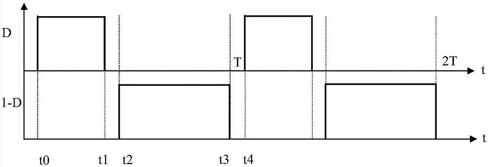
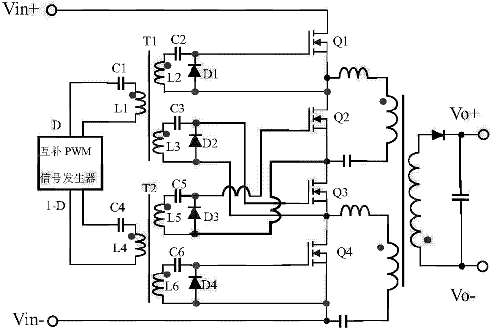
[0032] image 3 The circuit diagram of the first embodiment is shown, including input voltages Vin+ and Vin-, a complementary PWM signal generator, a driving transformer T1, a driving transformer T2, and a series asymmetrical half-bridge flyback circuit. The complementary PWM generator can send out a signal with a variable pulse width in a certain dead zone interval; the drive transformer T1 includes the first DC blocking capacitor C1, the primary winding L1, the second DC blocking capacitor C2, the first diode D1, the secondary side winding L2, the third DC blocking capacitor C3, the secondary winding L3, and the second diode D2; the driving transformer T2 is composed of the fourth DC blocking capacitor C4, the primary winding L4, the fifth DC blocking capacitor C5, the secondary winding L5, The third diode D3, the sixth DC blocking capacitor C6, the secondary winding L6, and the fourth diode D4 are composed; the series asymmetrical half-bridge flyback circuit is composed of ...

no. 2 example

[0044] Figure 4 It is a circuit diagram of the second example, which is different from the first embodiment in that resistors R1 , R2 , R3 and R4 are driven in series at the gate of each switch tube respectively. The specific connection relationship is: one end of the resistor R1 is connected to the other end of C2 and the cathode of the diode D1 at the same time, and the other end of R1 is connected to the gate of the switching tube Q1; one end of the resistor R2 is connected to the other end of C3 and the cathode of the diode D2 at the same time, The other end of R2 is connected to the grid of the switch tube Q3; one end of the resistor R3 is connected to the other end of C5 and the cathode of the diode D3 at the same time, and the other end of R3 is connected to the grid of the switch tube Q2; one end of the resistor R4 is connected to the other end of C6 at the same time and the cathode of the diode D4, and the other end of R4 is connected to the gate of the switching tub...

no. 3 example

[0047] Figure 5 It is the circuit diagram of the third example. The difference from the first embodiment is that the asymmetrical half-bridge flyback circuit consists of three pairs connected in series and has six switching tubes. The driving transformer T1 and the driving transformer T2 are respectively composed of four sets of windings. On the basis of the first embodiment, the secondary winding L7, capacitor C7, diode D5, and switch Q5 of the transformer T1 are added; the secondary winding L8, capacitor C8, diode D6, and switch Q6 of the transformer T2 are added. The connection relationship of the newly added components is: the end of the same name of the secondary winding L7 is connected to one end of the capacitor C7, the other end of the capacitor C7 is respectively connected to the cathode of the diode D5 and the gate of the switching tube Q5, and the opposite end of the secondary winding L7 is respectively connected to The anode of the diode D5 is connected to the sou...


PUM


Abstract

The invention discloses an asymmetric half-bridge flyback drive circuit, and the circuit comprises a complementary PWM generator, two drive transformers, and a series asymmetric flyback circuit. The separation of the drive transformers enables on / off switching tubes of the circuit to be respectively controlled, thereby improving the quality of a drive signal, and reducing the false triggering caused by the level changes. The dead zone time between the switching tubes is mainly controlled by a complementary signal because of the separated winding, thereby enabling the impact on the dead zone from the drive transformers to be the minimum. In a wide-range and high-input-voltage switching power application, the circuit, compared with the prior art, enables the reliability of a product to be improved.

Description

technical field [0001] The invention relates to the field of switching converters, in particular to an asymmetrical half-bridge flyback drive circuit. Background technique [0002] The rapid development of the field of power electronics has made the application of high-frequency switching power supplies more and more extensive. The input terminals of traditional industrial and civil switching power supplies often need to take power from the grid. After passing through the internal rectification and filtering circuit of the power supply, it becomes a higher DC power, and then input to the power conversion circuit to become a low-voltage DC power to provide power for the load. In order to adapt to the grid standards of different countries, the general two-phase AC input switching power supply has an input voltage range of 85VAC to 264VAC, and the DC voltage after rectification and filtering is about 120VDC to 373VDC. For the switching power supply used in this occasion, accor...

Claims


Application Information

Patent Timeline
Patent Type & Authority Applications(China)
IPC IPC(8): H02M1/088H02M1/38H02M3/335
CPCH02M1/083H02M1/088H02M1/38H02M3/33569H02M1/0058H02M1/385Y02B70/10
Inventor 宋建峰金若愚刘湘
Owner MORNSUN GUANGZHOU SCI & TECH
Learn More