
Angle detection device, rotating body and motor system

An angle detection and rotation angle detection technology, applied in the field of detection, can solve the problems of the unfavorable influence of the consistency of the resolver, the inability to measure the rotation angle of the rotor normally, and the disconnection.

Pending Publication Date: 2017-10-20
苏州昱泽智能科技有限公司
View PDF10 Cites 2 Cited by
  • Summary
  • Abstract
  • Description
  • Claims
  • Application Information

AI Technical Summary

Problems solved by technology

In the process of long-distance transmission, it is easy to be interfered by surrounding signals, which will adversely affect the detection accuracy, especially in the case of strong surrounding interference, which may lead to the failure to measure the rotation angle of the rotor normally
[0004] In the current resolver, there are multiple sets of windings on the stator detection teeth, usually three sets of windings, which makes the manufacturing process very complicated, and the consistency of the resolver is adversely affected due to the different positions of the windings; at the same time, due to the same There are multiple sets of windings on the sub-detection teeth. In the process of production and use, problems such as winding short circuit and disconnection are likely to occur due to vibration and shock, which will lead to failure of the resolver and poor reliability.
[0005] The existing resolver is basically an inductive resolver, and its signal processing device is poorly compatible with the inductive resolver. Therefore, the signal processing technology more suitable for the inductive resolver has strong research significance and application value.

Method used


Image

  • Angle detection device, rotating body and motor system
  • Angle detection device, rotating body and motor system
  • Angle detection device, rotating body and motor system

Examples


no. 1 example

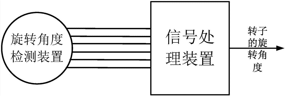
[0090] The angle detecting device includes a rotation angle detecting means and a signal processing means. The rotation angle detection device only includes a detection coil system. figure 1 Shown is a schematic diagram of the overall structure of the angle detection device.

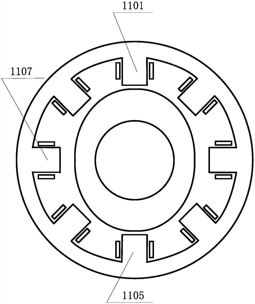
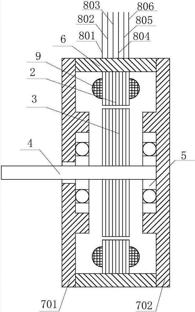
[0091] In this embodiment, the number of teeth detected by the stator of the rotation angle detection device is 8, and the number of salient poles of the rotor is 2 (set according to the number of teeth detected by the stator is 8*K, and the number of salient poles of the rotor is N; wherein, K and N are both positive integers. Therefore, in this embodiment, K is equal to 1, and N is equal to 2). figure 2 Shown is a schematic cross-sectional view of the stator and rotor of the rotation angle detection device. The stator includes a stator core, and the rotor includes a rotor core. Both the stator core and the rotor core are formed by stamping silicon steel sheets. In this embodiment, 8 stator detecti...

no. 2 example

[0121] In this embodiment, the angle detection device includes a rotation angle detection device and a signal processing device. The rotation angle detection device only includes a detection coil system. The overall structural diagram of the angle detection device can be borrowed from the first embodiment figure 1 .

[0122] In this embodiment, the number of stator detection teeth of the rotation angle detection device is 8, and the number of salient poles of the rotor is 2. In addition, in the rotation angle detection device, 8 stator decoupling teeth are provided, no coils are wound on the stator decoupling teeth, and the material of the stator decoupling teeth is magnetically permeable material. Image 6Shown is a schematic cross-sectional view of the stator and rotor of the rotation angle detection device. The stator includes a stator core, and the rotor includes a rotor core. Both the stator core and the rotor core are formed by stamping silicon steel sheets. In this...

no. 3 example

[0132] In this embodiment, the angle detection device includes a rotation angle detection device and a signal processing device. The rotation angle detection device only includes a detection coil system. The overall structural diagram of the angle detection device can be borrowed from the first embodiment figure 1 .

[0133] In this embodiment, the number of stator detection teeth of the rotation angle detection device is 8, and the number of salient poles of the rotor is 8. At the same time, a stator auxiliary tooth is provided on the two outer sides of the overall stator detection tooth (a total of 2 stator auxiliary teeth are provided). No coil is wound on the stator auxiliary tooth, and the material of the stator auxiliary tooth is a magnetic material. In addition, in this embodiment, the span of the stator yoke is less than 360 degrees. Figure 7 Shown is a schematic cross-sectional view of the stator and rotor of the rotation angle detection device. The stator includ...


PUM


Abstract

The invention provides an angle detection device, a rotating body and a motor system, which belongs to the technical field of detection. The angle detection device comprises a rotation angle detection device and a signal processing device. The rotation angle detection device comprises at least one set of detection coil system. Each set of detection coil system comprises at least four rows of multi-arm bridge circuits which are connected in parallel and are composed of a number of coils. Two lead wires are led out from two contacts, which are connected in parallel, of the multi-arm bridge circuits and are used as excitation leads. A lead wire is led out from each contact of upper and lower arms of each row of arms leads and is used as a signal lead wire. The signal processing device comprises an excitation circuit, a signal collection circuit and an angle calculation circuit. The differential signals of two signal lead wires and the differential signals of other two signal lead wires vary with the rotation angle of a rotor. The rotating body comprises the angle detection device and the rotating body. According to the invention, the measuring accuracy and the reliability are high; signal processing and calculating can be effectively carried out on an inductive rotation transformer; and the structure is simple.

Description

technical field [0001] The invention belongs to the technical field of detection, and relates to a detection device, in particular to an angle detection device, a rotating body and a motor system. Background technique [0002] Industries such as electric vehicles, industrial automation, robotics, textile machinery and aerospace all rely on high-performance control of rotating electrical machines, requiring motor rotation angle sensors and often requiring them to be used in high-temperature environments. Currently, photoelectric angle encoders are widely used because they can easily detect the rotation angle of motors. However, this kind of photoelectric angle encoder contains photoelectric components and semiconductor devices, so it cannot be used in high temperature environments. A resolver is a sensor that can detect rotation angles. Since it does not use a photoelectric conversion device, it can be used in a higher temperature environment. [0003] The existing inductive...

Claims


Application Information

Patent Timeline
Patent Type & Authority Applications(China)
IPC IPC(8): H02K11/225H02K11/33
CPCH02K11/225H02K11/33
Inventor 高翔
Owner 苏州昱泽智能科技有限公司
Learn More