Frequency domain decomposition based single image defogging acceleration method
A single image, frequency domain decomposition technology, applied in image enhancement, image analysis, image data processing and other directions, can solve the problems of large data processing volume, poor real-time performance, low computing efficiency, etc., to achieve high computing efficiency and short computing time. Effect
- Summary
- Abstract
- Description
- Claims
- Application Information
AI Technical Summary
Problems solved by technology
Method used
Image
Examples
specific Embodiment 1
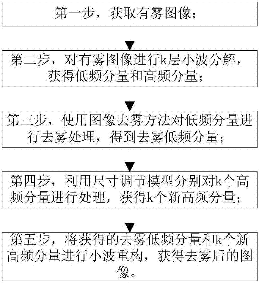
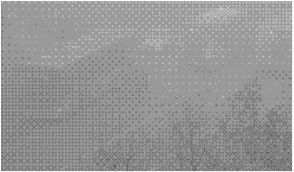
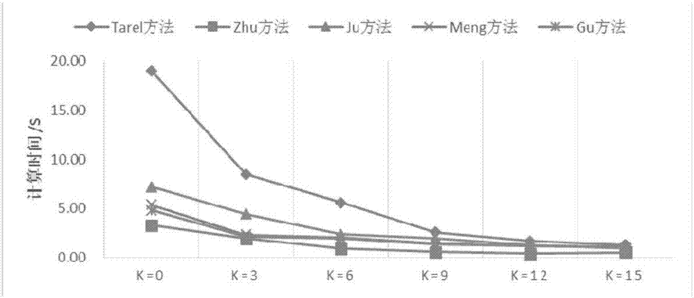
[0043] Obtaining a foggy image such as figure 2 As shown, the resolution of the image is 845×496; considering the computational complexity, the simplest Haar wavelet transformation method in wavelet transformation is preferred, and the foggy image is decomposed by three layers of wavelets to obtain one low-frequency component and three High-frequency components; use the Tarel method to defog the low-frequency components; use the size adjustment model to adjust the three high-frequency components; finally, perform wavelet reconstruction on the obtained defogged low-frequency components and three new high-frequency components to obtain For the image after dehazing, record the calculation time for obtaining the image after dehazing. The rest remain unchanged. In the second step, 6-layer, 9-layer, 12-layer and 15-layer wavelet decomposition is performed on the foggy image respectively. In the third step, the Zhu method, Ju method, Meng method and Gu method are used to remove the ...
specific Embodiment 2
[0044] Obtaining a foggy image such as Figure 4 As shown, the resolution of the image is 768×497. Three layers of wavelet decomposition is performed on the foggy image to obtain one low-frequency component and three high-frequency components. The Tarel method is used to dehaze the low-frequency component, and the three high-frequency components are dehazed. The frequency components are adjusted, and finally the obtained defogged low-frequency components and three new high-frequency components are wavelet reconstructed to obtain the defogged image, and the calculation time for obtaining the defogged image is recorded. The rest remain unchanged. In the second step, 6-layer, 9-layer, 12-layer and 15-layer wavelet decomposition is performed on the foggy image respectively. In the third step, the Zhu method, Ju method, Meng method and Gu method are used to remove the low frequency components. Fog processing, record the corresponding calculation time to obtain the image after defog...
specific Embodiment 3
[0045] Obtaining a foggy image such as Image 6 As shown, the resolution of the image is 400×600, and the foggy image is decomposed by 3-layer wavelet to obtain 1 low-frequency component and 3 high-frequency components, and the Tarel method is used to dehaze the low-frequency component, and the 3 high-frequency components are dehazed. The frequency components are adjusted, and finally the obtained defogged low-frequency components and three new high-frequency components are wavelet reconstructed to obtain the defogged image, and the calculation time for obtaining the defogged image is recorded. The rest remain unchanged. In the second step, 6-layer, 9-layer, 12-layer and 15-layer wavelet decomposition is performed on the foggy image respectively. In the third step, the Zhu method, Ju method, Meng method and Gu method are used to remove the low frequency components. Fog processing, record the corresponding calculation time to obtain the image after defogging, the result is as f...
PUM
 Abstract
Description
Claims
Application Information
 - R&D Engineer
- R&D Manager
- IP Professional
- Industry Leading Data Capabilities
- Powerful AI technology
- Patent DNA Extraction
Browse by: Latest US Patents, China's latest patents, Technical Efficacy Thesaurus, Application Domain, Technology Topic, Popular Technical Reports.
© 2024 PatSnap. All rights reserved.Legal|Privacy policy|Modern Slavery Act Transparency Statement|Sitemap|About US| Contact US: help@patsnap.com


