Microscopic imaging system

A microscopic imaging and imaging lens technology, which is applied in microscopes, optics, instruments, etc., can solve the problems of limited data acquisition speed, and achieve the effects of improving collection capabilities, enhancing information transmission capabilities, and fast pixel microscopic imaging

Inactive Publication Date: 2017-10-20
TSINGHUA UNIV
View PDF7 Cites 6 Cited by
  • Summary
  • Abstract
  • Description
  • Claims
  • Application Information

AI Technical Summary

Problems solved by technology

However, these two methods have their own limitations, and the improvement of data acquisition speed is limited.

Method used


Image

  • Microscopic imaging system
  • Microscopic imaging system
  • Microscopic imaging system

Examples


Embodiment Construction

[0020] Embodiments of the present invention are described in detail below, examples of which are shown in the drawings, wherein the same or similar reference numerals designate the same or similar elements or elements having the same or similar functions throughout. The embodiments described below by referring to the figures are exemplary only for explaining the present invention and should not be construed as limiting the present invention.

[0021] A microscopic imaging system according to an embodiment of the present invention will be described below with reference to the accompanying drawings.

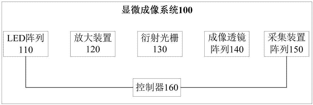
[0022] figure 1 is a structural diagram of a microscopic imaging system according to an embodiment of the present invention.

[0023] Such as figure 1 As shown, the microscopic imaging system 100 according to an embodiment of the present invention includes: an LED array 110 , an amplifying device 120 , a diffraction grating 130 , an imaging lens array 140 , an acquisition device ...


PUM


Abstract

The invention discloses a microscopic imaging system that comprises an LED array including light with a plurality of wavelengths; an amplification device disposed on one side of the LED array; a diffraction grating disposed on one side of the amplification device and satisfying conditions that light with different wavelengths is refracted at different angles and that the light with the same wavelength can be refracted to the same angle; an imaging lens array and an acquisition device array that are arranged on one side of the diffraction grating, wherein the light of one wavelength is provided with an imaging lens and acquisition device group, and respective imaging lens and acquisition device groups are placed at different spatial positions so that the imaging lenses and the acquisition devices acquire light with corresponding wavelength; and a controller connected with the LED array and the acquisition device array so that the acquisition device array performs synchronous data acquisition while the LED array transforms an illumination mode. The microscopic imaging system can acquire multiple sample images at one time and greatly enhances an information transmission capability.

Description

technical field [0001] The invention relates to the technical field of microscopic imaging, in particular to a microscopic imaging system. Background technique [0002] In optical imaging, field of view and resolution have always been important indicators for evaluating the performance of imaging systems. But in a traditional optical system, the spatial bandwidth product (SBP) is limited (generally only a few million pixels), that is to say, it is impossible to obtain a wide field of view and high resolution in the imaging process of. At present, researchers are increasingly applying computational methods to optical imaging, realizing some optical imaging methods that can simultaneously obtain wide field of view and high resolution, and are increasingly used in biological research. The FPM (Fourier ptychograhicmicroscopy, frequency-domain collage microscopy) system is such a method, which can obtain a sample image of one billion pixels without mechanical scanning, which ca...

Claims


Application Information

Patent Timeline
Patent Type & Authority Applications(China)
IPC IPC(8): G02B21/06G02B21/36
CPCG02B21/06G02B21/367
Inventor 戴琼海周游吴嘉敏
Owner TSINGHUA UNIV
Why Eureka
Try Eureka