
Real-time optical fiber positioning device based on central opening type four-quadrant detector, and positioning method thereof

A four-quadrant detector and center position technology, which is used in measurement devices, testing optical fiber/optical waveguide equipment, instruments, etc., can solve problems such as the inability to meet optical fiber positioning, and achieve real-time closed-loop monitoring and feedback, good coupling effect.

Active Publication Date: 2017-10-20
HOHAI UNIV
View PDF5 Cites 7 Cited by
  • Summary
  • Abstract
  • Description
  • Claims
  • Application Information

AI Technical Summary

Problems solved by technology

[0005] Generally speaking, the current optical fiber positioning systems have not successfully realized the real-time closed-loop monitoring and feedback of optical fibers, and cannot meet the needs of higher-precision optical fiber positioning.

Method used


Image

  • Real-time optical fiber positioning device based on central opening type four-quadrant detector, and positioning method thereof
  • Real-time optical fiber positioning device based on central opening type four-quadrant detector, and positioning method thereof
  • Real-time optical fiber positioning device based on central opening type four-quadrant detector, and positioning method thereof

Examples


Embodiment Construction

[0026] The technical solution of the present invention will be further introduced below in conjunction with the accompanying drawings and specific implementation methods.

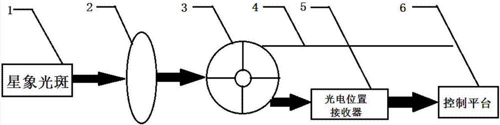
[0027] The specific embodiment of the present invention discloses a real-time optical fiber positioning device based on a center-opening four-quadrant detector, such as figure 2 shown, including:

[0028] Astrology spot 1 received from the telescope system;

[0029] Converging lens 2: used to converge the star image spot 1, and the converged laser light is irradiated onto the center-opening four-quadrant detector 3 to form a spot;

[0030] Center opening four-quadrant detector 3: a small hole is opened in the center to determine the center position of the light spot, and then send the center position of the light spot to the photoelectric position receiver 5; figure 1 is a schematic diagram of a center-opening four-quadrant detector 3, wherein figure 1 (a) is a schematic diagram of the unbiased afterglo...


PUM


Abstract

The invention discloses a real-time optical fiber positioning device based on a central opening type four-quadrant detector. The device comprises the components of an astrological light spot which is received from a telescope system; a convergent lens which is used for converging the astrological light spot, wherein the convergent laser is irradiated to the central opening type four-quadrant detector for forming a light spot; the central opening type four-quadrant detector which is provided with a small opening at the center and is used for determining a light spot center position and transmits the light spot center position to a photoelectric position receiver; the photoelectric position receiver which is used for receiving the light spot center position that is transmitted from the central opening type four-quadrant detector and transmits the light spot center position to a control platform; the control platform which is used for adjusting the position of the optical fiber according to the light spot center position; and the optical fiber of which one end is inserted into the central small opening of the central opening type four-quadrant detector. The invention further discloses a method for positioning by means of the real-time optical fiber positioning device. The real-time optical fiber positioning device and the positioning method successively realize real-time closed-loop monitoring and feedback of the optical fiber.

Description

technical field [0001] The invention relates to the technical field of optical fiber positioning, in particular to a real-time optical fiber positioning device and positioning method based on a center-opening four-quadrant detector. Background technique [0002] Since the 1980s, optical fiber technology has gradually penetrated into astronomical observations, and astronomy has entered the era of "multi-band, large sample, and high information content". Large-scale multi-objective optical fiber spectral surveys have become a breakthrough in astronomical observations. The spectra of hundreds of thousands, millions, or even tens of millions of celestial bodies can obtain richer celestial body information that imaging sky surveys cannot provide. [0003] The international multi-objective fiber optic spectrometer telescopes or sky survey programs mainly include 2dF, AAΩ, 6dF of the Anglo-Australian Observatory (AAO) in Australia, SDSS of the United States, GAIA of the European Sp...

Claims


Application Information

Patent Timeline
Patent Type & Authority Applications(China)
IPC IPC(8): G01M11/00
CPCG01M11/30
Inventor 邹华王淋正张美玲孟小枫刘金升
Owner HOHAI UNIV
Learn More