A method for selecting a control strategy for a converter in an energy regenerative system

A control strategy and energy feedback technology, applied in power lines, vehicle components, parallel feeding arrangements for a single network, etc., can solve problems such as insufficient real-time performance, overvoltage of traction network, energy loss, etc., to reduce energy interaction and ensure normal operation. running effect

Active Publication Date: 2019-05-24
KEHUA DATA CO LTD
View PDF8 Cites 0 Cited by
  • Summary
  • Abstract
  • Description
  • Claims
  • Application Information

AI Technical Summary

Problems solved by technology

Rail transit facilities are mainly powered by electric traction. Since rail transit facilities start and brake frequently, it is easy to cause energy loss. In order to improve the energy utilization rate of rail transit facilities, a regenerative energy feedback system is usually used to recover the energy generated by the braking of rail transit facilities. Recycling, as well as the energy required for instant replenishment of rail transit facilities; in order to achieve this function, traditional regenerative energy feedback systems often use the method of real-time monitoring of the bus voltage of the traction network to achieve, but this method still has a certain hysteresis , the real-time performance is not enough, resulting in the regenerative energy feedback system may not be able to recover the braking energy in time during the braking process, resulting in overvoltage of the traction network and damage to the rail transit facilities; The rail transit equipment cannot be started smoothly due to the energy

Method used


Image

  • A method for selecting a control strategy for a converter in an energy regenerative system
  • A method for selecting a control strategy for a converter in an energy regenerative system
  • A method for selecting a control strategy for a converter in an energy regenerative system

Examples


Embodiment Construction

[0021] In order to make the technical problems, technical solutions and beneficial effects to be solved by the present invention clearer and clearer, the present invention will be further described in detail below in conjunction with the accompanying drawings and embodiments. It should be understood that the specific embodiments described here are only used to explain the present invention, not to limit the present invention.

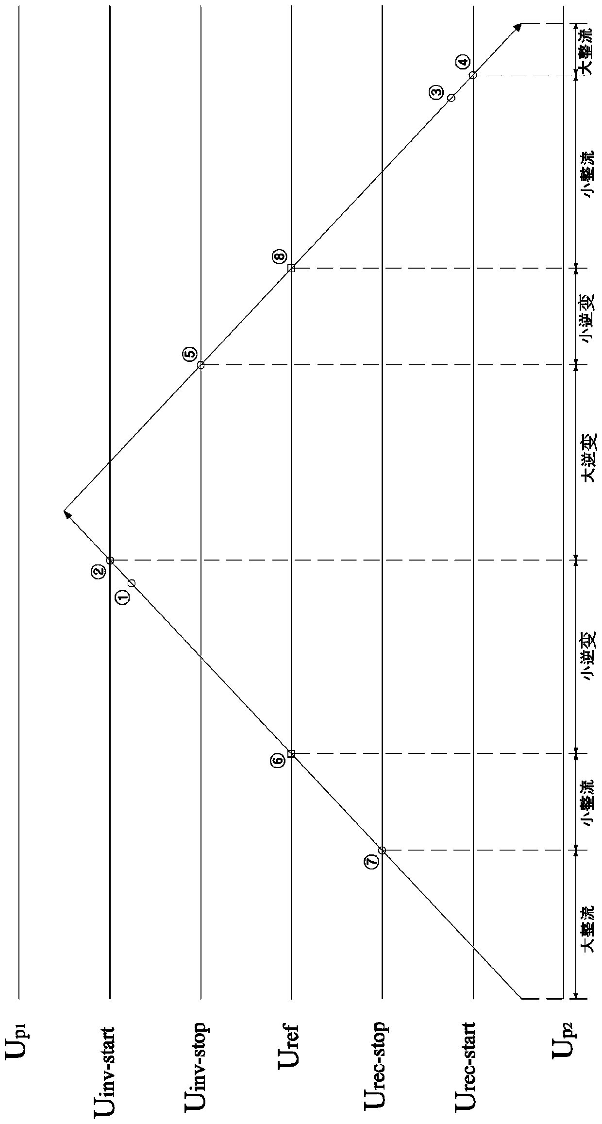
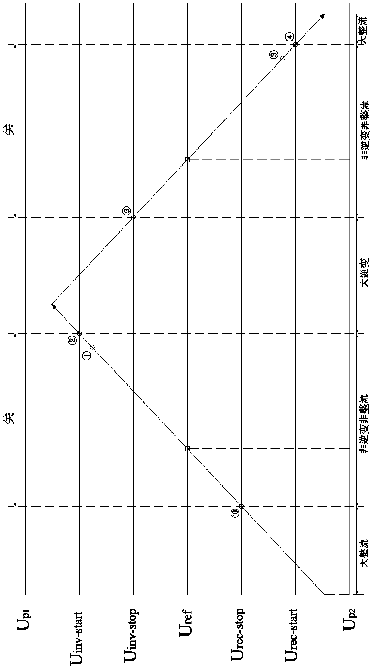
[0022] Such as Figure 1 to Figure 4 As shown, the converter control strategy in the method for selecting the control strategy of the energy feedback system converter in the embodiment of the present invention includes inverter, rectification and non-inversion non-rectification; inverter refers to controlling the energy feedback system The converter in the traction network makes the busbar of the traction network transmit energy to the power grid with high power; rectification refers to the process of controlling the converter in the energy feedback sys...


PUM


Abstract

The invention discloses a method for selecting control strategies of a converter in an energy feedback system. The control strategies of the converter in the energy feedback system comprise inversion, rectification and non-inversion and non-rectification. The method comprises the following steps that the bus voltage of a traction network is measured and stored in a first storage unit, and the initial control strategy of the converter is set into non-inversion and non-rectification and stored in a second storage unit; and the bus voltage of the traction network is measured every manually-set first time interval, after the measurement voltage value is measured every time, the sub process is executed, and the executing period of the sub process does not exceed the first time interval. By adoption of the method for selecting control strategies of the converter in the energy feedback system, energy feedback starting or stopping can be achieved in time or even ahead of time, and it is guaranteed that braking energy can be timely fed back or supplied through the traction network, so that the condition that due to overvoltage, rail transportation facilities are damaged, or due to excessive absorption of traction network energy, operation of the rail transportation facilities is affected is effectively avoided.

Description

technical field [0001] The invention relates to the field of control strategies of converters in energy feedback systems, in particular to a method for selecting a control strategy for converters in energy feedback systems. Background technique [0002] At present, rail transit has increasingly become a transportation facility commonly used by people for daily travel, and it plays a major role in transportation. Rail transit facilities are mainly powered by electric traction. Since rail transit facilities start and brake frequently, it is easy to cause energy loss. In order to improve the energy utilization rate of rail transit facilities, a regenerative energy feedback system is usually used to recover the energy generated by the braking of rail transit facilities. Recycling, as well as the energy required for instant replenishment of rail transit facilities; in order to achieve this function, traditional regenerative energy feedback systems often use the method of real-tim...

Claims


Application Information

Patent Timeline
Patent Type & Authority Patents(China)
IPC IPC(8): B60M3/00H02J3/38
CPCB60M3/00H02J3/38
Inventor 杜伟戴永辉谢启源
Owner KEHUA DATA CO LTD
Why Eureka
Try Eureka