
Ultrasonic automatic welding equipment

An automatic welding and ultrasonic technology, applied in the mechanical field, can solve the problems of low work efficiency, low work efficiency, high production cost, etc., and achieve the effect of improving the degree of automation, reasonable structure design and high work efficiency

Active Publication Date: 2017-10-20
嘉兴日昌汽车配件股份有限公司
View PDF7 Cites 8 Cited by
  • Summary
  • Abstract
  • Description
  • Claims
  • Application Information

AI Technical Summary

Problems solved by technology

[0003] In the early days of cable ultrasonic welding, manual methods were used. The workers stacked the cables and connectors on the workbench and aligned them with the welding head, and started welding manually. After completion, the cables and connectors were moved, and the welded products were stacked. Then proceed to the next product welding. This welding method not only has a high error rate but also takes a long time, and the work efficiency is low.
[0004] A semi-automatic airbag wire harness welding machine has appeared in the existing market, through manual feeding, the welding machine senses the product for welding, but after the completion, it still needs to manually pick up the material and sort out the product, which is more labor-intensive and the work efficiency is not high; And the quantity that this welding mechanism can weld at one time is less, and the production cost is high

Method used


Image

  • Ultrasonic automatic welding equipment
  • Ultrasonic automatic welding equipment
  • Ultrasonic automatic welding equipment

Examples


Embodiment Construction

[0034] The technical solutions of the present invention will be further described below in conjunction with the embodiments and the accompanying drawings.

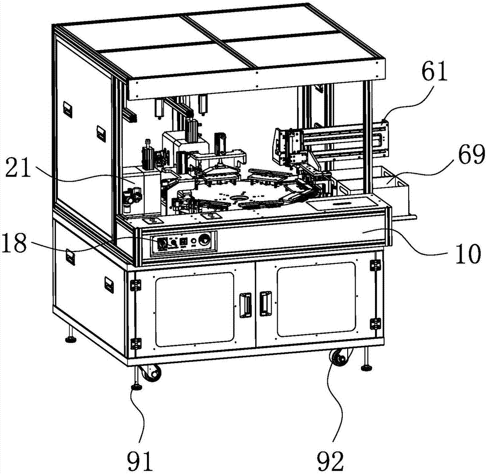
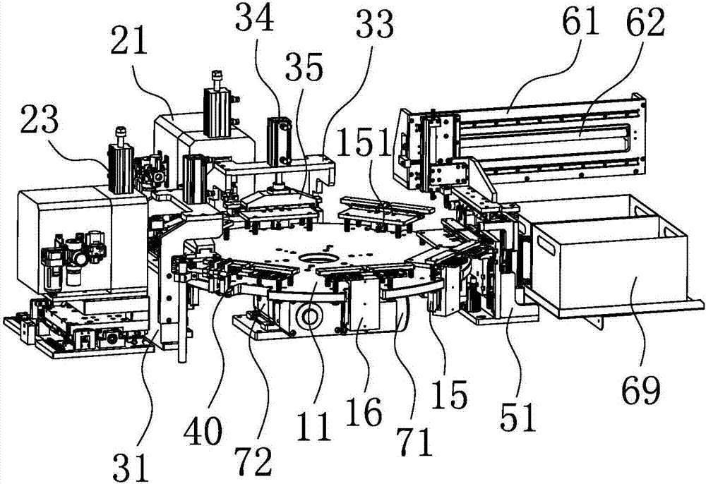
[0035] Such as figure 1 with figure 2 As shown, the ultrasonic automatic welding equipment includes:

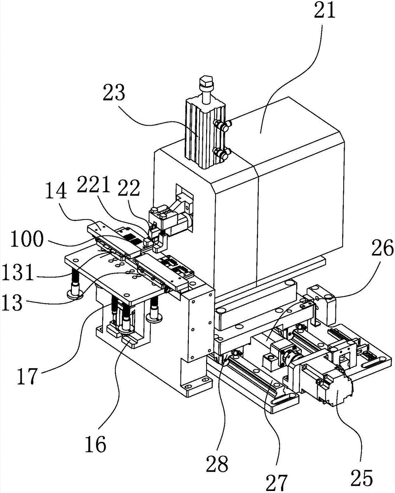
[0036] The frame 10 has a turntable 11 arranged in a disk shape, and a plurality of stations evenly distributed are arranged on the turntable 11, and a plurality of cables 100 are clamped on each station;

[0037] There is at least one welding assembly, and an ultrasonic generator 24 is arranged in the welding assembly. When the rotary table 11 drives the cable 100 to rotate to the welding assembly, the welding assembly welds the cable 100 through ultrasonic waves;

[0038] The stripping assembly is arranged around the rotary table 11 with the welding assembly, and the stripping assembly can separate the welded cable 100 from the station;

[0039] The material taking component is set corresponding to the material stri...


PUM


Abstract

The invention provides ultrasonic automatic welding equipment, belongs to the technical field of machinery, and solves the problem that the welding effect of conventional equipment for cable welding is not ideal. The ultrasonic automatic welding equipment comprises a rack, at least one welding assembly, a stripping assembly and a material taking assembly, wherein the rack is provided with a disc-shaped rotating table; a plurality of uniformly-distributed stations are arranged on the rotating table; a plurality of cables are clamped on each station; an ultrasonic generator is arranged in the welding assembly; when the cables are driven by the rotating table to rotate to the welding assembly, the welding assembly welds the cables in an ultrasonic manner; together with the welding assembly, the stripping assembly encircles the rotating table; through the stripping assembly, the welded cables can be separated from the stations; and the material taking assembly is arranged corresponding to the stripping assembly, and can receive the cables separated by the stripping assembly and convey the cables to a specified position. The ultrasonic automatic welding equipment provided by the invention has the characteristics of being high in automation degree and welding quality.

Description

technical field [0001] The invention belongs to the technical field of machinery, and relates to an ultrasonic automatic welding device, in particular to an ultrasonic automatic welding device for welding cables. Background technique [0002] The cable used to connect the airbag and the main board in the car is installed in the airbag of the car. The cable has good flexibility, has the functions of bending resistance and tensile resistance, and can withstand cold and high temperature. In order to realize the connection function, the cable needs to be welded. The welding work of cables is often carried out with the help of ultrasonic waves. Through ultrasonic high-frequency vibrations, the energy generated by high-frequency vibrations is used to combine the same or dissimilar metals under appropriate pressure through cold grinding and horizontal movement to infiltrate the surface molecules of the materials. The wiring harness is quickly welded to achieve the purpose of wel...

Claims


Application Information

Patent Timeline
Patent Type & Authority Applications(China)
IPC IPC(8): B23K20/10B23K20/26
CPCB23K20/10B23K20/26Y02W30/82
Inventor 南日
Owner 嘉兴日昌汽车配件股份有限公司
Learn More