
Local smoothing method for discrete machining path with controllable error and passing a given tool position

A technology of processing paths and tool points, which is applied in the field of high-speed and high-precision CNC machining, can solve the problems of inability to retain discrete processing path tool point information, loss of original contour feature information, and difficulty in taking into account continuity, etc., to improve kinematics performance Effect

Active Publication Date: 2019-06-25
DALIAN UNIV OF TECH
View PDF5 Cites 2 Cited by
  • Summary
  • Abstract
  • Description
  • Claims
  • Application Information

AI Technical Summary

Problems solved by technology

This method satisfies the machining accuracy and the entire smooth path G 2 Continuous requirements, but the smooth path usually cannot pass through the tool points that make up the discrete processing path. The reason is that in the local smoothing algorithm, the transition curve is usually used to approximate the tool point of the discrete processing path twice, thus causing the original contour loss of feature information
By analyzing the existing discrete path fairing methods, it can be seen that global fairing is usually difficult to take into account the entire path G when ensuring the machining accuracy. 2 continuity requirements
Although local fairing satisfies the machining accuracy and G 2 Continuous requirements, but unable to retain the information of discrete machining path tool points
So far, the relevant literature has not been able to solve the problem of smoothing the discrete machining path through the tool position.

Method used


Image

  • Local smoothing method for discrete machining path with controllable error and passing a given tool position
  • Local smoothing method for discrete machining path with controllable error and passing a given tool position
  • Local smoothing method for discrete machining path with controllable error and passing a given tool position

Examples


Embodiment Construction

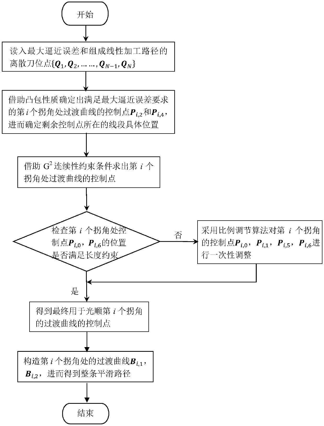
[0032] A flow chart of an inflection point smoothing method for a discrete path is shown in figure 1 shown. The present invention will be described in detail below in conjunction with specific embodiments. The following examples will help those skilled in the art to further understand the present invention, but do not limit the present invention in any form. It should be noted that those skilled in the art can make several modifications and improvements without departing from the concept of the present invention. These all belong to the protection scope of the present invention.

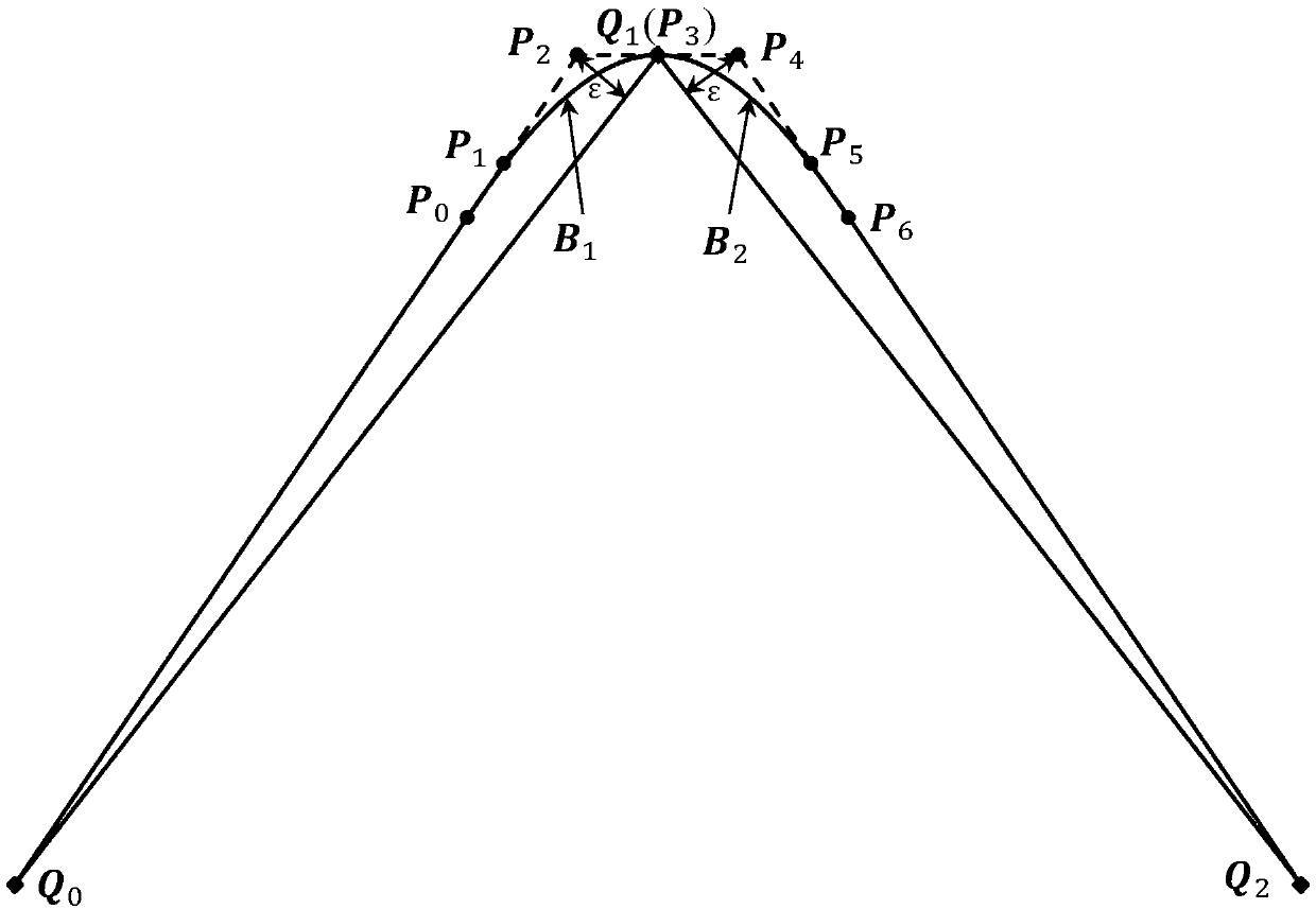
[0033] (a) Determine the specific position of the line segment where the control point of the transition curve that meets the maximum approximation error requirement is determined by means of the convex hull property. like figure 2 As shown, the inflection point Q 1 The vertices of two adjacent linear processing straight line segments are respectively (Q 0 ,Q 1 ) and (Q 1 ,Q 2 ), the allowa...


PUM


Abstract

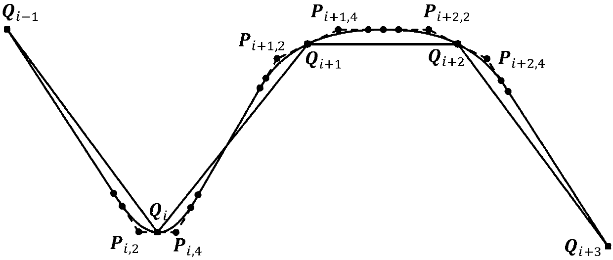
The invention discloses a local smoothing method having controllable errors and capable of passing predetermined cutter location points of a scattering processing path, and belongs to the high speed high precision numerical control processing field. Every corner of the scattering processing path adopts two cubic Bezier curves to be used as transition curves for the smoothing processing, and problems of routine scattering path processing such as low precision and easy speed fluctuation are solved. The concrete position of the control point of the transition curve satisfying a maximum approximation error requirement on a line segment is determined with help of convex hull property. Under conditions of G2 continuity restriction and line segment length restriction, the inverse computation of the control point of the transition curve is carried out. According to the acquired control point, a dual-cubic Bezier curve used for the path smoothing is finally acquired. By adopting the local smoothing method, the G2 continuity of the path after the smoothing is achieved, and by comparing with other path smoothing algorithms, processing precision is guaranteed, and the method can pass the cutter location points used to form the scattering processing path.

Description

technical field [0001] The invention relates to a local smoothing method for a discrete machining path with controllable errors and passing through a given tool position point, belonging to the field of high-speed and high-precision numerical control machining. Background technique [0002] In the field of NC machining, the path used for actual machining is usually a series of tool position points discretized on the theoretical curve tool path according to the given machining accuracy, so these tool position points usually contain the feature information of the original contour. However, due to the discontinuity of the tangent vector and curvature at the connection points of adjacent linear segments of the linear path composed of discrete tool positions, the fluctuation of feed rate and the decline of machined surface quality will inevitably occur. Therefore, the traditional discrete processing path is not suitable for the field of high-speed and high-precision CNC machining...

Claims


Application Information

Patent Timeline
Patent Type & Authority Patents(China)
IPC IPC(8): G05B19/404
CPCG05B19/404G05B2219/35408
Inventor 孙玉文徐富阳郭东明
Owner DALIAN UNIV OF TECH
Learn More