
Heat exchanging plate, machining method and heat exchanger

A processing method and heat exchange plate technology, applied in the field of heat exchange plates and heat exchangers, can solve problems affecting system efficiency and economy, uneven flow distribution, increased compression power consumption, etc., to increase effective heat transfer area, save power consumption, and reduce the effect of channel resistance

Active Publication Date: 2017-10-17
NO 719 RES INST CHINA SHIPBUILDING IND
View PDF12 Cites 10 Cited by
  • Summary
  • Abstract
  • Description
  • Claims
  • Application Information

AI Technical Summary

Problems solved by technology

However, the highly compact arrangement and micro-scale channels of the printed circuit board micro-channel heat exchanger will greatly reduce the size of the heat exchanger, but will also cause a sharp increase in the resistance of the heat exchanger, uneven flow distribution, and excessive local temperature of the plate. These problems not only lead to increased compression power consumption, but also affect the efficiency and economy of the entire system

Method used


Image

  • Heat exchanging plate, machining method and heat exchanger
  • Heat exchanging plate, machining method and heat exchanger
  • Heat exchanging plate, machining method and heat exchanger

Examples


Embodiment Construction

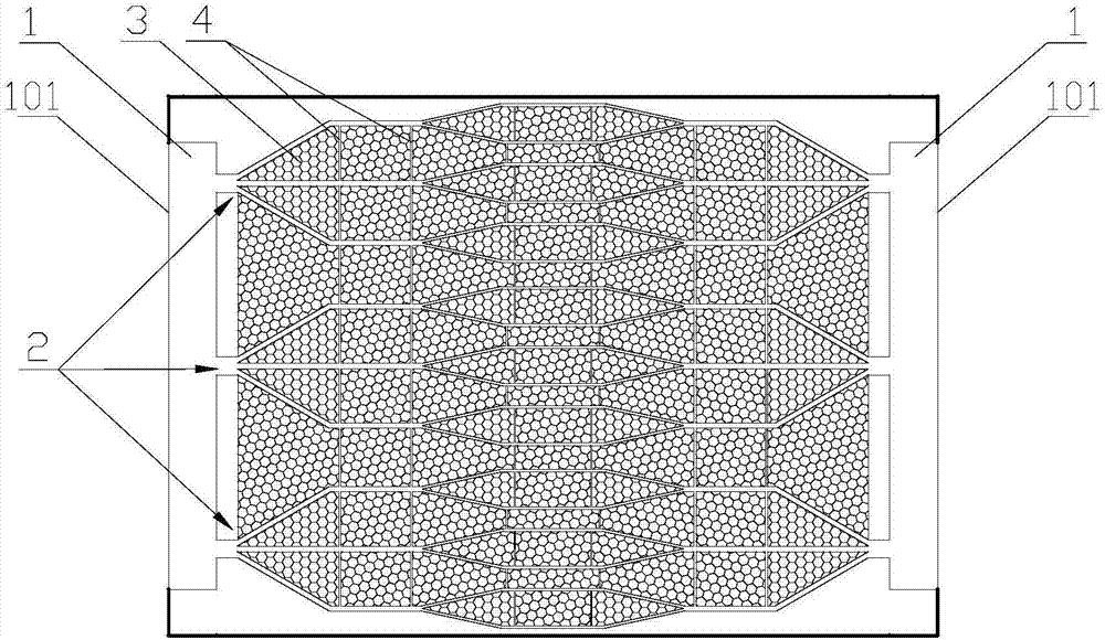
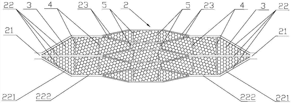
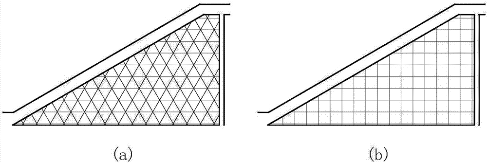
[0034] In the embodiment of the present invention, the front and back sides of the same heat exchange plate are machined, chemically and laser etched to form a mesh including a graded flow channel 2 , a secondary flow channel 4 and a mesh between the graded flow channel 2 and the secondary flow channel 4 The vein-shaped fluid distribution structure of the flow channel 3 is used as a fluid heat transfer microchannel for heat exchange of fluids (such as supercritical fluids), and the positions of the vein-shaped heat transfer microchannels on the front and back of the same heat exchange plate correspond. Therefore, The heat transfer microchannel with the fractal feature of leaf veins produces more and more branches, which not only greatly increases the convective heat transfer area and enhances the convective heat transfer effect, but also uses the leaf vein bionic structure to reduce the flow resistance of the working fluid. On the premise of consumption, the working medium is t...


PUM


Abstract

The invention discloses a heat exchanging plate, a machining method and a heat exchanger, and relates to the field of heat exchanging equipment. Two flow gathering grooves and a groove-shaped flow channel are formed in the first surface of the heat exchanging plate, and the two flow gathering grooves are located at the two ends of the heat exchanging plate correspondingly; the groove-shaped flow channel comprises at least one hierarchic flow channel and net-shaped flow channels, wherein each hierarchic flow channel is located between the two flow gathering grooves in a communicating mode, and comprises two main flow channels which mutually communicate with the two flow gathering grooves correspondingly, and the two main flow channels communicate with each other through at least two first branch flow channels; the net-shaped flow channels are formed between adjacent first branch flow channels and are in fluid communication with the first branch flow channels; and meanwhile, the area of the cross section of each net-shaped flow channel is smaller than the area of the cross section of each first branch flow channel, and the hierarchic flow channels and net-shaped flow channels form leaf-vein-shaped fluid distributing structures. According to the heat exchanging plate, the machining method and the heat exchanger, through combined action of main driving force of the hierarchic flow channels and capillary force of the net-shaped flow channels, the distribution evenness of fluid is effectively improved, the effective heat transfer area is increased, so that the flow rate of the fluid under the same flow quantity is reduced, and therefore resistance is reduced.

Description

technical field [0001] The invention relates to the field of heat exchange equipment, in particular to a heat exchange plate, a processing method and a heat exchanger. Background technique [0002] With the rapid development of the fourth-generation high-temperature reactor technology and clean thermal power technology, the supercritical fluid Brayton cycle, which is highly matched to it, has become a research hotspot at home and abroad, and has a great tendency to replace the existing steam Rankine cycle. Because the Brayton cycle has the characteristics of high heat recovery and is under the condition of gas-gas heat exchange, the supercritical fluid heat exchanger has become the largest equipment in the power system, and its volume accounts for more than 90% of the total equipment volume of the power system. At the same time, the performance of the supercritical fluid heat exchanger is of great significance to the integration, stability, controllability and safety of the ...

Claims


Application Information

Patent Timeline
Patent Type & Authority Applications(China)
IPC IPC(8): F28F3/02
CPCF28F3/02
Inventor 赵振兴刘洲洋林原胜吴君柳勇白凡劳星胜
Owner NO 719 RES INST CHINA SHIPBUILDING IND
Learn More