
Brake caliper for disk brake

A disc brake and brake caliper technology, applied in the field of brake calipers, can solve problems such as uneconomical

Active Publication Date: 2017-10-13
ZF CV SYST EURO BV
View PDF11 Cites 1 Cited by
  • Summary
  • Abstract
  • Description
  • Claims
  • Application Information

AI Technical Summary

Problems solved by technology

It is not economical to use lost foam to cast molds

Method used


Image

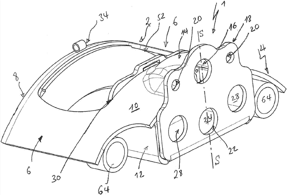
  • Brake caliper for disk brake
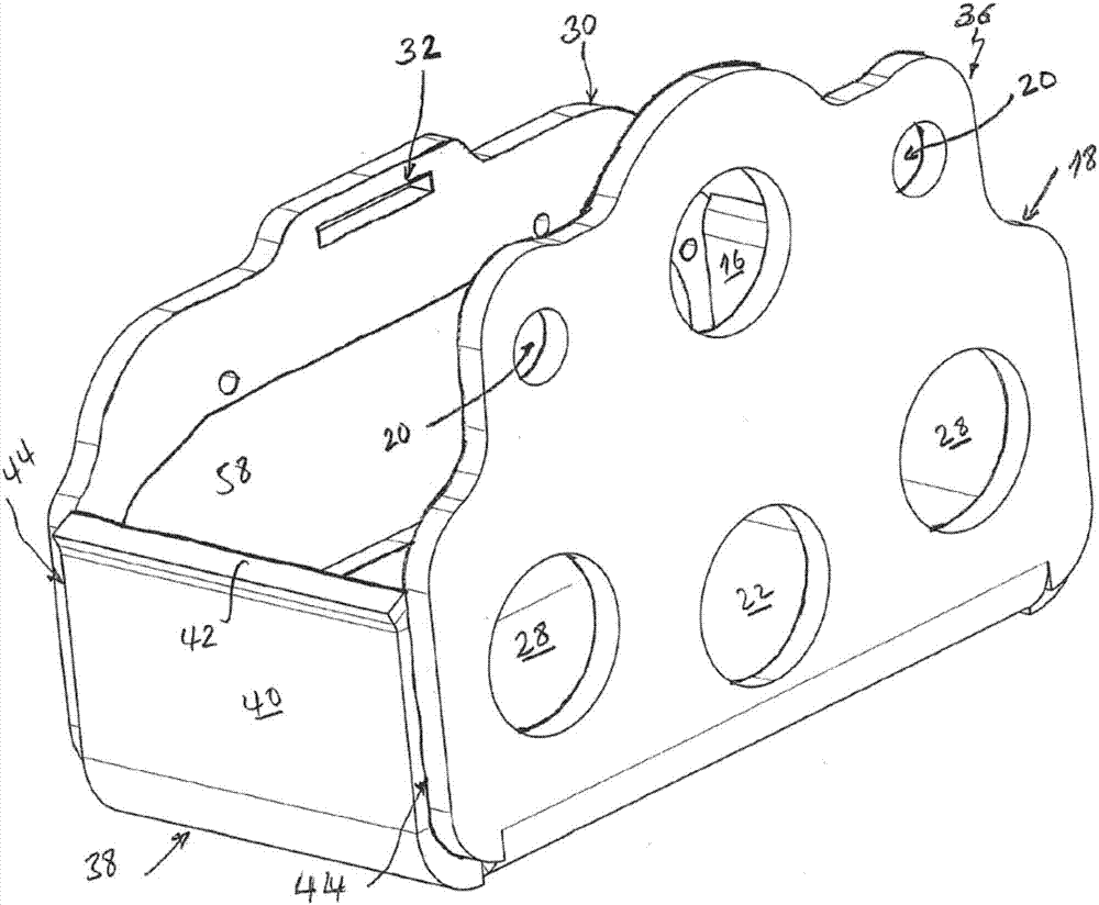
  • Brake caliper for disk brake
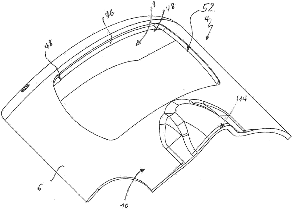
  • Brake caliper for disk brake

Examples


Embodiment Construction

[0036] figure 1 is a perspective view of one embodiment of a brake caliper, the main components of which are described below. This general description applies to all embodiments.

[0037] The brake caliper denoted by the reference symbol 1 has a caliper frame 2 consisting only of sheet metal elements that have been cut or punched, deep-drawn and connected, usually by welding. The tongs frame 2 comprises a cover section 4 which is constructed as a one-piece sheet metal element and forms a tensioning rod 6 and a tongs back 8 connecting the two tensioning rods 6 together. The tie rod 6 is detached from a cover 10 formed by the cover section 4 , which delimits on the top side and covers a housing 12 , which will be described further below. Such as figure 1As shown, this housing 12 is mirror-symmetrical about an axis of symmetry denoted by reference symbol S. The cover 10 has an upper cover dome 14 which covers a central upper bore 16 which is opened in the outer section 18 and...


PUM


Abstract

A brake caliper for a disk brake, has a caliper frame (2) which is configured suitably for engaging over the brake disk, and a housing (12) for receiving a brake application mechanism for applying a braking force to the brake disk. The housing (12) can be configured from an outer segment (18), an inner segment (30) which extends substantially parallel to the outer segment (18), and bottom and cover segments (38; 4) which extend between the outer and inner segments and are manufactured in each case from sheet metal, wherein at least two segments (18, 30, 38; 4, 18, 30) are configured by way of a unitary sheet metal element and / or locating bearings and floating bearings (64) are formed by way of sheet metal tubes (72) which are formed in one piece by way of bending of at least one of the metal sheets which configure at least one segment (74).

Description

technical field [0001] The invention relates to a brake caliper for a disc brake. The invention relates in particular to a brake caliper for a disc brake of a truck. The brake caliper has a caliper frame configured to span the brake disc, and a housing for housing a compression mechanism for compressing the disc brake. Background technique [0002] Brake calipers of this type usually have a caliper frame constructed as an injection-molded part, which forms the covering of the housing and usually forms the tensioning rods between the housing and the caliper back arranged opposite this housing, these tensioning rods will The caliper back is connected to the fixed side end of the brake caliper and thrust-bearing, in particular a brake plate, which is supported on the caliper back during braking. [0003] A part of such a brake caliper is known from EP 0 108 860 A1, which part consists of two sheet metal parts arranged opposite one another. These sheet metal parts form housin...

Claims


Application Information

Patent Timeline
IPC IPC(8): F16D55/226F16D55/227F16D65/56F16D65/18F16D125/32
CPCF16D55/226F16D55/227F16D65/183F16D65/568F16D2125/32F16D2200/0008F16D2055/0025F16D2055/002
Inventor 约尔格·埃伯特
Owner ZF CV SYST EURO BV
Learn More