
Oil-in-water emulsion oil holdup distribution electrical imaging measurement method

A technology of liquid oil holdup and electrical imaging, which is applied in the direction of measuring devices, scientific instruments, and analytical materials, etc., can solve the problem of large measurement blind area, reduce the interfacial tension between oil and water, and fail to meet the requirements of real-time capture of local oil holdup distribution of pipeline cross-section and other problems to achieve the effect of improving measurement accuracy and reducing measurement blind spots

Inactive Publication Date: 2017-10-13
TIANJIN UNIV
View PDF3 Cites 6 Cited by
  • Summary
  • Abstract
  • Description
  • Claims
  • Application Information

AI Technical Summary

Problems solved by technology

Since surfactants can greatly reduce the interfacial tension between oil and water phases, the size of oil bubbles in oil-water emulsions is usually on the order of microns, which also brings great challenges to the measurement of local oil holdup of oil-in-water emulsions.
In addition, the traditional radially movable (array) conductivity probe measurement method can only achieve local oil holdup measurement in a single direction in the pipeline, and its measurement blind area is large, and the dispersion holdup distribution of the emulsion is mostly non-uniform Therefore, the traditional radial conductivity probe array sensor cannot meet the requirements of capturing the local oil holdup distribution of the pipeline section in real time

Method used


Image

  • Oil-in-water emulsion oil holdup distribution electrical imaging measurement method
  • Oil-in-water emulsion oil holdup distribution electrical imaging measurement method
  • Oil-in-water emulsion oil holdup distribution electrical imaging measurement method

Examples


Embodiment Construction

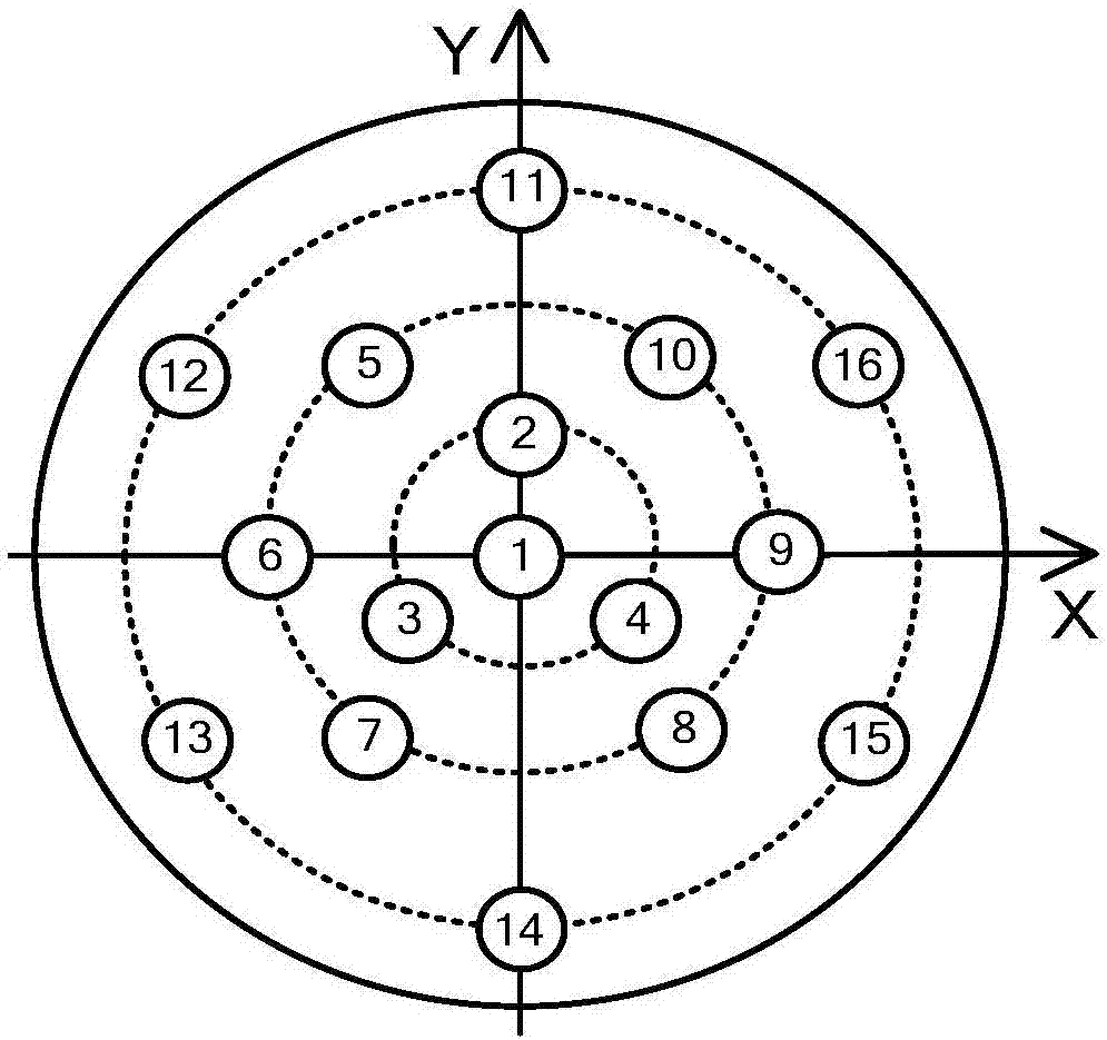
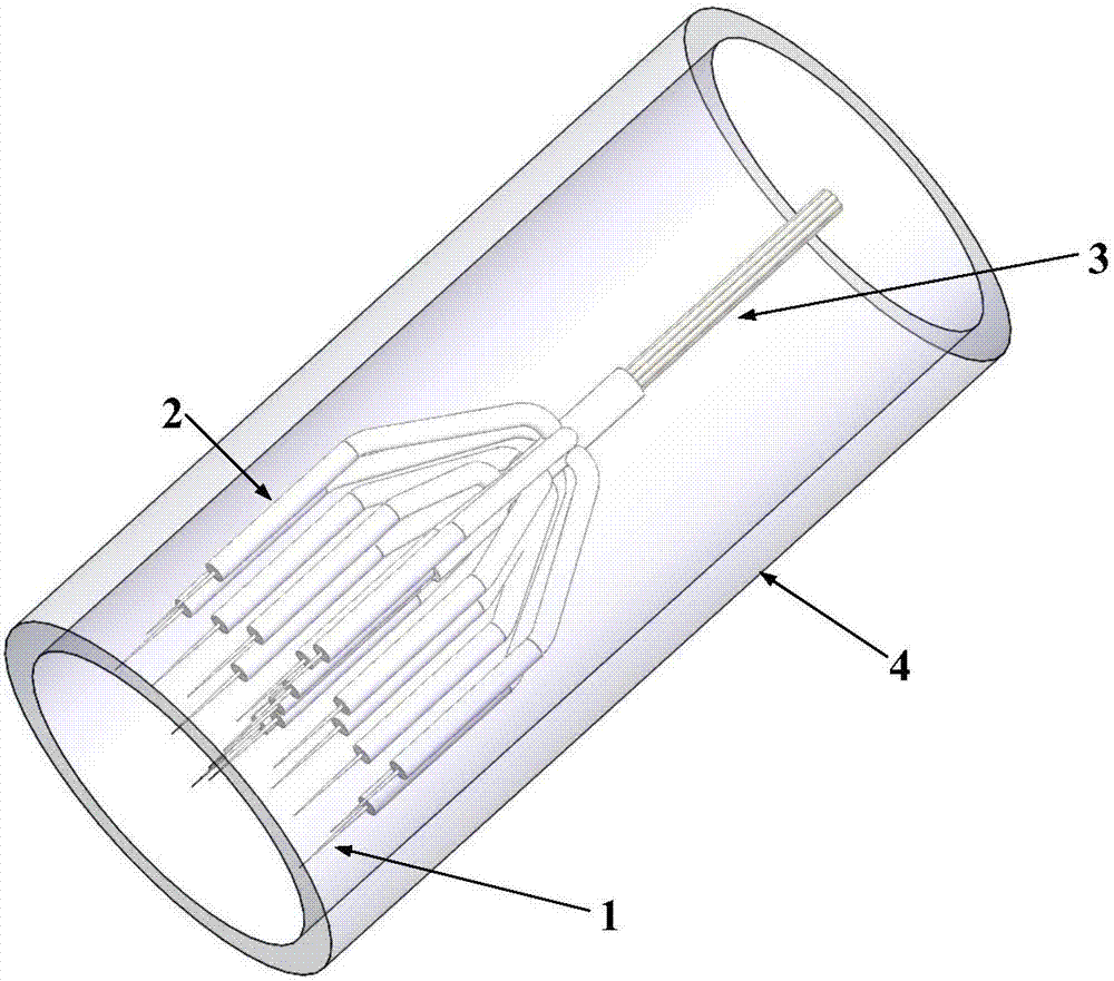
[0015] In order to investigate the distribution behavior of the oil-in-water emulsion in the pipe section under the action of surfactants, the innovative idea of ​​the present invention is to break through the measurement mode of the radial probe in a single direction by using a distributed conductivity probe measurement method, and A probe measurement method suitable for capturing micron-sized droplets of oil-in-water emulsions is proposed. In the measurement method, sixteen single-conductivity probe sensors are placed in the small pipe diameter measurement pipeline after the current collection. The sixteen probes are divided into 4 rings in the pipeline. The first ring contains only one probe, and the second The ring is composed of 3 probes, the third ring is composed of 6 probes, and the fourth ring is composed of 6 probes. The position of the probe of each ring is reasonably placed through the geometric structure, and the local oil retention rate of the pipe section can be ...


PUM

PropertyMeasurementUnit
diameteraaaaaaaaaa
diameteraaaaaaaaaa

Abstract

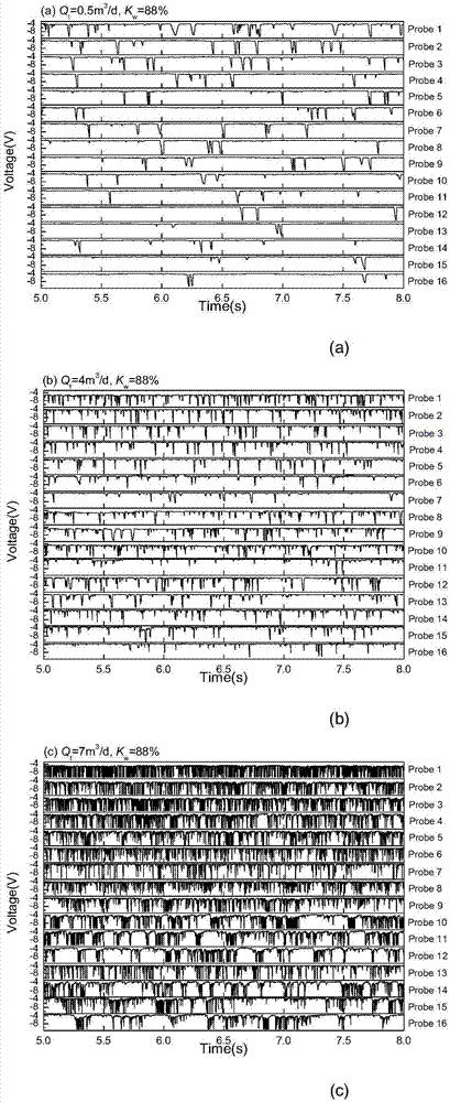
The invention relates to an oil-in-water emulsion oil holdup distribution electrical imaging measurement method. A sensor used in the invention comprises multi-path conducting probe sensors placed in the positions of multiple concentric rings in afflux measurement pipes with small pipe diameters in distributed states, and each conducting probe sensor comprises an excitation source probe and a receiving source metal sleeve, wherein the first ring comprises first-path conducting probe sensors, and the conducting probes sensor located on the concentric rings are all uniformly distributed; while measuring, output signals of each path conducting probe sensor are collected, original measurement signals are converted into corresponding square wave signals by using a self-adjustment double-threshold method, the square wave signals are taken as signals to be processed and calculated to obtain the local oil holdup, and later, a cubic spline interpolation algorithm is reused to carry out three-dimensional imaging on pipeline cross-section oil holdup distribution so as to reconstruct distribution behaviors of oil-in-water emulsion oil holdup on a pipeline cross section under the effect of a surfactant.

Description

Technical field [0001] The invention relates to a method for measuring the local oil retention rate of an oil-in-water emulsion under the action of a surfactant in the field of oilfield dynamic monitoring. Background technique [0002] Due to the long-term use of water injection exploitation methods, onshore oilfield exploitation has entered the middle and late stages of exploitation characterized by low flow velocity and high water cut. In order to improve crude oil recovery, chemical flooding technology based on surfactant flooding has been widely used in oil fields. Realizing the accurate measurement of the local oil holdup of oil-in-water emulsions under the action of surfactants is of great significance for oil well dynamic monitoring and optimization of downhole fluid production profile production logging phase holdup sensors. [0003] The addition of surfactants will greatly change the rheological properties of the mixed fluid, resulting in a complicated mixed-phase flow ph...

Claims


Application Information

Patent Timeline
Patent Type & Authority Applications(China)
IPC IPC(8): G01N27/00
CPCG01N27/00
Inventor 金宁德韩云峰翟路生任英玉谷宇黄梓浩刘东洋韩廷昊
Owner TIANJIN UNIV
Learn More