Experiment instrument for measuring liquid viscosity coefficient by pipe clamp photogates

A technology of viscosity coefficient and photoelectric gate, which is applied in the direction of instruments, measuring devices, scientific instruments, etc., can solve problems such as difficult to achieve relative 180° horizontal placement, unable to complete experimental measurement on time, unable to guarantee vertical incidence, etc., to achieve control manufacturing Efficiency, reduced manufacturing costs, and reduced manufacturing accuracy requirements

Active Publication Date: 2017-10-13
INNER MONGOLIA UNIV OF SCI & TECH
View PDF23 Cites 2 Cited by
  • Summary
  • Abstract
  • Description
  • Claims
  • Application Information

AI Technical Summary

Problems solved by technology

[0004] 1) Both the laser transmitter and the laser receiver must be fixed on the cylindrical support rod by the top screw, which is not stable and easy to loosen; and it is difficult to achieve a relative 180°horizontal placement of the two
[0005] 2) The upper and lower sets of laser beams must be in the same vertical plane, so that the falling steel balls can block the two laser beams in turn and measure the falling time. The above process requires many adjustment steps, which is time-consuming and labor-intensive
[0006] 3) Both pairs of laser photoelectric gates are set outside the measuring cylinder, so the vertical incidence cannot be guaranteed. The laser is emitted by the air through the glass measuring cylinder filled with liquid, and four times of refraction occurs, which is no longer a straight line propagation; at this time, it is necessary Adjust the positions of the two receivers again until they both receive signals; and the two laser beams must be on the same vertical plane. Repeatedly adjusting the positions of the lasers and receivers during the experiment is time-consuming and labor-intensive, even 2- 3 The adjustment was not in place for two hours, and the experimental measurement could not be completed on time. In the end, the students could only use the stopwatch to manually time the time, resulting in large errors in the experimental results
[0007] 4) The traditional instrument is to put a heavy hammer in the middle of the beam of the instrument, and the position of the tip of the heavy hammer is used as the center point of the measuring cylinder. This kind of positioning is difficult to place the measuring cylinder directly under the conduit in the beam, and the steel ball thrown cannot be along the central axis of the measuring cylinder. whereabouts

Method used


Image

  • Experiment instrument for measuring liquid viscosity coefficient by pipe clamp photogates
  • Experiment instrument for measuring liquid viscosity coefficient by pipe clamp photogates
  • Experiment instrument for measuring liquid viscosity coefficient by pipe clamp photogates

Examples


Embodiment Construction

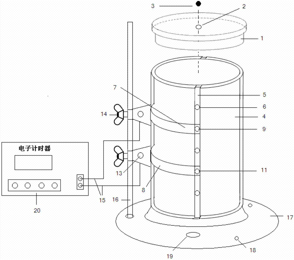
[0045] The invention is a measuring instrument for viscosity coefficient by falling ball method, which uses modern semiconductor laser technology combined with single-chip microcomputer timing method to measure the falling time of steel balls with different diameters, and uses Stokes formula to measure the viscosity coefficient of liquid. The characteristics of the instrument are concise structure, easy operation, intuitive phenomenon, accurate measurement data, small measurement error, good repeatability and low cost. The specific technical scheme is as follows:

[0046] Take the technical solution including two tube clamp photogates as an example. according to figure 1 It can be seen that the tester includes a measuring cylinder cover (1), a central hole (2), a steel ball (3), a measuring cylinder (4), a groove (5), a tapered groove (6), a first tube clamp photoelectric gate (7), The second tube clip photoelectric gate (8), the first laser emitting head (9), the first lase...


PUM

PropertyMeasurementUnit
diameteraaaaaaaaaa

Abstract

The invention relates to an experiment instrument for measuring liquid viscosity coefficient by pipe clamp photogates. The experiment instrument comprises a steel bead, a measuring cylinder, a measuring cylinder cover and at least two pipe clamp photogates; two grooves are formed in the two sides of the measuring cylinder oppositely; at least two pairs of conical grooves are formed in the grooves; each pipe clamp photogate comprises two clamping arms, a laser transmitter, a laser emergent head, a laser receiver, a laser receiving head, an adjusting screw and a fixing device; a laser emergent head and the laser receiving head are movably arranged at the free ends of the two clamping arms; the laser emergent head and the laser receiving head are circular truncated cone-shaped, so as to be matched with the conical grooves in shape. The experiment instrument avoids the tedious operation that the position of the receiver needs to be adjusted again after multiple-time refraction of laser, the laser emergent head and the laser receiving head are inserted into the conical grooves to realize automatic positioning, and the measuring precision and the efficiency are improved.

Description

technical field [0001] The invention relates to the technical field of liquid viscosity coefficient measurement, and also belongs to the field of experimental instruments, in particular to an experimental instrument device for measuring liquid viscosity coefficient with a tube clamp photogate. Background technique [0002] Liquid viscosity is a measure of the viscosity of a liquid, an important physical quantity describing the internal friction properties of a liquid, and is related to the nature, temperature and flow rate of the liquid (non-Newtonian liquid). It characterizes the ability of a liquid to resist deformation, and it is only manifested when there is relative motion in the liquid. In industrial and agricultural production and scientific research, it is often necessary to know the viscosity of liquids. Liquid viscosity is often used to identify the quality and use of various lubricating oils, and to judge the combustion performance and use of various fuel oils. I...

Claims


Application Information

Patent Timeline
Patent Type & Authority Applications(China)
IPC IPC(8): G01N11/12
CPCG01N11/12
Inventor 毛爱华鞠向明蔡禄
Owner INNER MONGOLIA UNIV OF SCI & TECH
Why Eureka
Try Eureka