
Method for assembling steel structure framework and composite lightweight floor slab module

A steel structure frame, composite technology, applied in building construction, building material processing, construction and other directions, can solve the problems of reducing construction work space, low construction efficiency, occupying more space, etc., to shorten the construction period and improve the construction. Speed, avoid the effect of secondary decoration

Active Publication Date: 2017-10-13
重庆中迎智居装配式建筑科技有限公司
View PDF3 Cites 4 Cited by
  • Summary
  • Abstract
  • Description
  • Claims
  • Application Information

AI Technical Summary

Problems solved by technology

[0004] Among them, the assembly method of the prefabricated floor in the steel frame structure usually includes the installation of the prefabricated floor support system, the hoisting of the prefabricated floor, and subsequent processing steps; when the prefabricated floor is installed, not only is it temporarily fixed, but also the level of the components needs to be corrected. The traditional The prefabricated floor slab support system is several rows of support frames erected on the floor, which support and position the floor slab in the vertical direction. In this way, due to the large number of vertical supports, it takes up more space and reduces the construction work space. It has a great impact on the working surface of other operations carried out at the same time, and the process of setting and adjusting the height of the vertical support requires more manpower, takes a long time, and the construction efficiency is low

Method used


Image

  • Method for assembling steel structure framework and composite lightweight floor slab module
  • Method for assembling steel structure framework and composite lightweight floor slab module
  • Method for assembling steel structure framework and composite lightweight floor slab module

Examples


Embodiment Construction

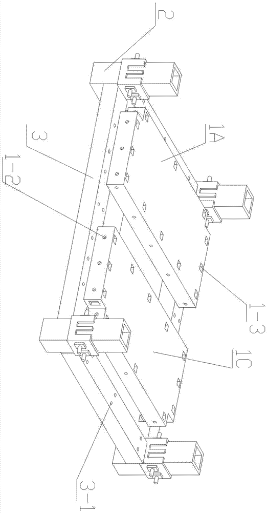
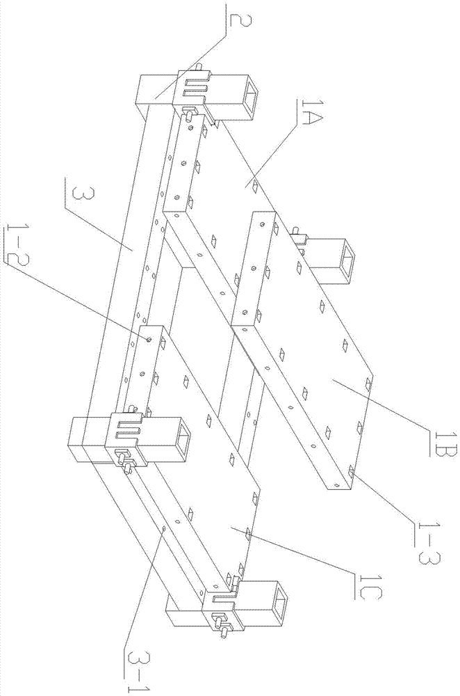
[0040] See attached Figure 1-8 A method for assembling a steel structure frame and a composite lightweight floor module, the method is based on a floor datum plane formed by the steel structure frame, and the method includes the following process steps:

[0041] 1) Manufacture floor modules for assembly according to architectural drawings 1: According to the preset connection parts and technical parameters of position and shape on the steel structure frame, used to manufacture floor modules for assembly 1. Process reserved process holes and equip on-site Connection fasteners for construction;

[0042] 2) The upper end surface of the load-bearing beam 3 in the steel structure frame forms the floor reference plane;

[0043] 3) Check the prefabricated steel column 2 and load-bearing beam 3 in the steel structure frame, the connecting parts, the connection position and the process assembly hole tolerance with the floor module 1, and prepare the adjusting gasket;

[0044] 4) Pos...


PUM


Abstract

The invention provides a method for assembling a steel structure framework and a composite lightweight floor slab module, and belongs to the technical field of assembling construction engineering. The method is based on a floor datum plane formed by a steel structure framework. The method comprises the following process steps: according to a construction drawing, manufacturing floor slab modules used for splicing; making the upper end face of a bearing beam in the steel structure framework form a floor datum plane; checking connecting components prefabricated on bearing steel columns and bearing beams in the steel structure framework, connecting positions, and tolerance of the connecting components with technical assembling holes of the floor slab module; by matched technical holes and connecting assemblies, respectively positioning a first floor slab sub-module and a tail floor slab sub-module in the floor slab module in slab hanging positions of corresponding bearing steel columns in the steel structure framework, to realize heavy load mount; laying an intermediate floor slab sub-module in space between the first floor slab sub-module and the tail floor slab sub-module; performing waterproofness treatment and decorative filling and repairing on junctions of the floor slab module and the bearing steel columns, junctions of the floor slab module and the bearing beam, and junctions of adjacent floor slab modules, and the technical holes.

Description

technical field [0001] The invention belongs to the technical field of assembly building engineering, and in particular relates to a method for assembling a steel structure frame and a composite light-weight floor module to form a floor plan. Background technique [0002] Steel frame structure is widely used in modern multi-storey residences, factories, shops, office buildings, hospitals, teaching buildings and hotels because of its advantages of flexible layout and large interior space. [0003] The steel frame structure building uses the steel structure skeleton to bear the weight of the whole building. In the frame formed by the steel skeleton, the frame is composed of load-bearing steel columns and load-bearing beams of the steel skeleton, and then filled with block walls and prefabricated floors to divide the internal use space. The overall weight of the building formed by block walls and prefabricated floors is borne by load-bearing steel columns and load-bearing beam...

Claims


Application Information

Patent Timeline
IPC IPC(8): E04G21/14
CPCE04G21/14
Inventor 牛智勇
Owner 重庆中迎智居装配式建筑科技有限公司
Learn More