Milling process damping calibration method based on operating modal analysis

A calibration method and working mode technology, applied in the direction of instruments, etc., can solve problems such as poor practicability and achieve good practicability.

Active Publication Date: 2017-10-10
NORTHWESTERN POLYTECHNICAL UNIV
View PDF10 Cites 5 Cited by
  • Summary
  • Abstract
  • Description
  • Claims
  • Application Information

AI Technical Summary

Problems solved by technology

[0005] In order to overcome the disadvantages of poor practicability of existing milling process damping calibration methods, the present invention provides a milling process damping calibration method based on working modal analysis

Method used


Image

  • Milling process damping calibration method based on operating modal analysis
  • Milling process damping calibration method based on operating modal analysis
  • Milling process damping calibration method based on operating modal analysis

Examples


Embodiment Construction

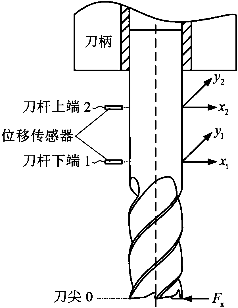
[0046] refer to Figure 1-6 . The specific steps of the milling process damping calibration method based on the working mode analysis in the present invention are as follows:

[0047] Step 1. Experimentally select a cemented carbide end mill with a radius of 6mm, a helix angle of 35°, a normal front angle of 10°, a relief angle of 5°, a radius of the tool tip arc of 20 μm, and a number of teeth of 4 in the three coordinates Vertical machining center performs down milling on aluminum alloy 7050-T7451. Attach the accelerometer to the tool tip 0, the lower end 1 of the tool bar and the upper end 2 of the tool bar, and strike the tool tip 0 with a force hammer, and extract the dominant mode parameters m in the x and y directions from the obtained frequency response curve x =0.3193kg, ζ sr,x = 1.79%, ω n,x = 1060Hz, and m y =0.3971kg, ζ sr,y = 2.35%, ω n,y = 1041Hz, where m x and m y is the modal mass at tip 0, ζ sr,x and ζ sr,y is the structural damping ratio at too...


PUM


Abstract

The invention discloses a milling process damping calibration method based on operating model analysis, and is used for solving the technical problem of poor practicability of an existing milling process damping calibration method. The technical scheme includes the following steps: first obtaining cutter-machine tool system model parameters; then carrying out a no-flutter-stable milling experiment, and measuring vibration signals in an upper position and a lower position in x and y directions of a milling cutter bar; and determining a power spectrum density matrix of the measured vibration signals at each frequency point, performing singular value decomposition on the matrix, then removing characteristic values corresponding to periodic cutting force, performing inverse Fourier transform on the corresponding larger characteristic values, and extracting an average damping coefficient on peak and valley values of an inverse transformation result. After the average damping coefficient is obtained, first cutting force and tool nose frequency response are utilized to obtain a too nose position vibration amplitude value, then the vibration amplitude value together with the average process damping coefficient is substituted into energy balance relational expressions established in the x and y directions, a milling process damping coefficient is calibrated, and he practicability is good.

Description

technical field [0001] The invention relates to a damping calibration method for milling process, in particular to a damping calibration method for milling process based on working mode analysis. Background technique [0002] The energy of vibration during cutting is absorbed by two forms of damping, one is the structural damping generated by the workpiece, tool-holder and machine tool system, and the other is the extrusion and friction between the tool flank and the workpiece resulting in process damping. In the process of drawing the stability lobe diagram, if only the structural damping is considered and the influence of the process damping is ignored, the stability prediction results deviate greatly from the experimental observations in the lower speed range. Therefore, the identification of process damping has important theoretical and engineering application value. [0003] The document "L. Tunc, E. Budak, Identification and modeling of process damping inmilling, Tra...

Claims


Application Information

Patent Timeline
Patent Type & Authority Applications(China)
IPC IPC(8): G01M7/00
CPCG01M7/00
Inventor 万敏冯佳张卫红马颖超杨昀
Owner NORTHWESTERN POLYTECHNICAL UNIV
Why Eureka
Try Eureka