Automatic firework barrel packaging machine

A technology for automatic packaging machines and fireworks canisters, which can be applied to fireworks, offensive equipment, weapon types, etc., and can solve problems such as manual manipulation of fireworks packaging.

Inactive Publication Date: 2017-10-10
肇庆市端州区麒诺机械科技有限公司
View PDF2 Cites 2 Cited by
  • Summary
  • Abstract
  • Description
  • Claims
  • Application Information

AI Technical Summary

Problems solved by technology

[0003] In order to solve the technical problem that the above-mentioned fireworks tube packaging still adopts manual manipulation, the present invention proposes an automatic packaging equipment for fireworks tubes

Method used


Image

  • Automatic firework barrel packaging machine
  • Automatic firework barrel packaging machine

Examples


Embodiment 1

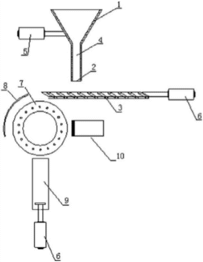
[0017] Such as figure 1 and figure 2 As shown, the automatic packaging machine for fireworks tubes in a preferred embodiment of the present invention includes a paper feeding mechanism 9 for wrapping paper, a tube feeding mechanism for fireworks tubes, and a drum-type sticker packaging mechanism 7, wherein the drum-feeding mechanism is located at the end of the drum-type sticker packaging mechanism 7 In the upper part, the paper feeding mechanism 9 is located at the lower part of the drum type sticker packaging machine 7. The paper feeding mechanism 9 is connected with an electric paper feeder 6. When the paper is reduced, the pallet on the upper part of the electric paper feeder 6 moves upward to allow the paper to The distance to the roller remains constant. The tube delivery mechanism includes a storage bin 1 with a firework tube outlet at the bottom and a fireworks tube receiving and conveying mechanism located under the storage bin 1 . The firework tube receiving and c...

Embodiment 2

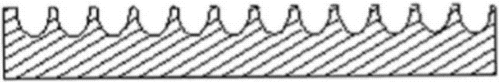
[0022] Such as figure 1 and figure 2 As shown, the difference from the first embodiment is that the conveyor belt or the conveyor plate 3 is a fixed flat plate, which becomes the carrier plate 3 . Fireworks tube outlet 2 is located close to the position directly above the drum-type sticker packaging mechanism 7, and the power device 6 of the fireworks tube receiving and transmitting mechanism becomes a push mechanism, and its front end is provided with a push rod. , pushed forward by the push rod to realize timing and quantitative feeding.

[0023] In order to help stabilize the posture of the fireworks tube, the outlet of the fireworks tube is located at 2 and one side of the pushing mechanism 6 is formed as a comb, and the other side is formed as an opening. The front part of the pushing mechanism 6 has several comb-shaped push rods corresponding to the comb-shaped outlet 2 , and is located at the front end of the outlet 2 of the fireworks tube. This facilitates maintain...


PUM


Abstract

The invention discloses an automatic firework barrel packaging machine which comprises a paper feeding mechanism of packing paper, a barrel feeding mechanism of a firework barrel, and a drum-type sticker packaging mechanism, wherein the barrel feeding mechanism is located at the upper part of the drum-type sticker packaging mechanism; the paper feeding mechanism is located at the lower part of the drum-type sticker packaging mechanism; the barrel feeding mechanism comprises a storage silo with a firework barrel outlet formed in the bottom, and a firework barrel receiving and delivery mechanism located below the storage silo; the drum-type sticker packaging mechanism is driven by an electric driving mechanism; a negative pressure compartment is formed below a housing of the external surface of the drum-type sticker packaging mechanism; the negative pressure compartment is connected with a getter pump; and a plurality of fine pores which are used for sucking sticker sheets and communicate with the negative pressure compartment are formed in the external surface of the housing in a dispersive manner. The problem that traditional firework barrel packaging adopts manual operation is solved, and automatic packaging of the firework barrel can be realized.

Description

technical field [0001] The invention relates to fireworks manufacturing equipment, in particular to a fireworks tube manufacturing equipment. Background technique [0002] Fireworks have a long history of thousands of years in our country. People often set off fireworks in festivals and various festive programs to show a festive atmosphere. Traditionally, fireworks are made by hand. In recent years, with the development of industry and technology, some procedures of fireworks production can be made by machinery, such as making mud, building medicine, and feeding tubes. Mechanical production of fireworks improves production efficiency, reduces costs, and is also conducive to improving safety control during the production of fireworks. However, there are still some procedures that are still manual, and the packaging of fireworks tubes is one of them. [0003] The present invention proposes an automatic packaging device for fireworks tubes in order to solve the technical prob...

Claims


Application Information

Patent Timeline
Patent Type & Authority Applications(China)
IPC IPC(8): F42B4/30
CPCF42B4/30
Inventor 江钰琪
Owner 肇庆市端州区麒诺机械科技有限公司
Why Eureka
Try Eureka