A coaxial structure of supercritical carbon dioxide centrifugal compressor and axial flow turbine

A centrifugal compressor and carbon dioxide technology, applied in mechanical equipment, steam engine devices, machines/engines, etc., can solve the problems of increased cost, difficult matching of high-speed motors, high motor requirements, etc., to reduce equipment manufacturing and system operating costs, and improve application Sex and economy, and the effect of reducing the quality of the whole machine

Active Publication Date: 2020-03-31
XI AN JIAOTONG UNIV
View PDF4 Cites 0 Cited by
  • Summary
  • Abstract
  • Description
  • Claims
  • Application Information

AI Technical Summary

Problems solved by technology

A very important problem exists in the current design of supercritical carbon dioxide impeller machinery. Due to the special physical properties of supercritical carbon dioxide, the designed impeller has a small diameter and a high speed, so a high-speed motor must be used to drive the compressor. However, the use of high-speed motor drives has problems such as complex systems, high requirements on motors, and increased costs.
Based on the above reasons, the present invention proposes a coaxial structure of a centrifugal compressor using supercritical carbon dioxide as a working medium and an axial flow turbine, and the axial flow turbine directly drives the compressor, which has the characteristics of simple system, compact structure and high efficiency , while solving the problems of difficult matching of high-speed motors and high manufacturing costs, effectively reducing equipment manufacturing and operating costs

Method used


Image

  • A coaxial structure of supercritical carbon dioxide centrifugal compressor and axial flow turbine
  • A coaxial structure of supercritical carbon dioxide centrifugal compressor and axial flow turbine
  • A coaxial structure of supercritical carbon dioxide centrifugal compressor and axial flow turbine

Examples


Embodiment Construction

[0027] The embodiments of the present invention will be described in detail below in conjunction with the accompanying drawings. This embodiment is based on the technical solution of the present invention, and provides detailed implementation methods and specific operating procedures, but the scope of protection of the present invention is not limited to the following embodiments. .

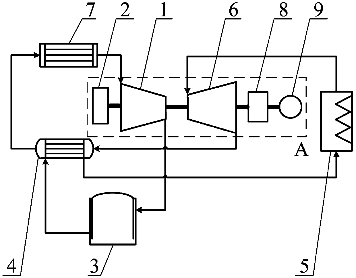
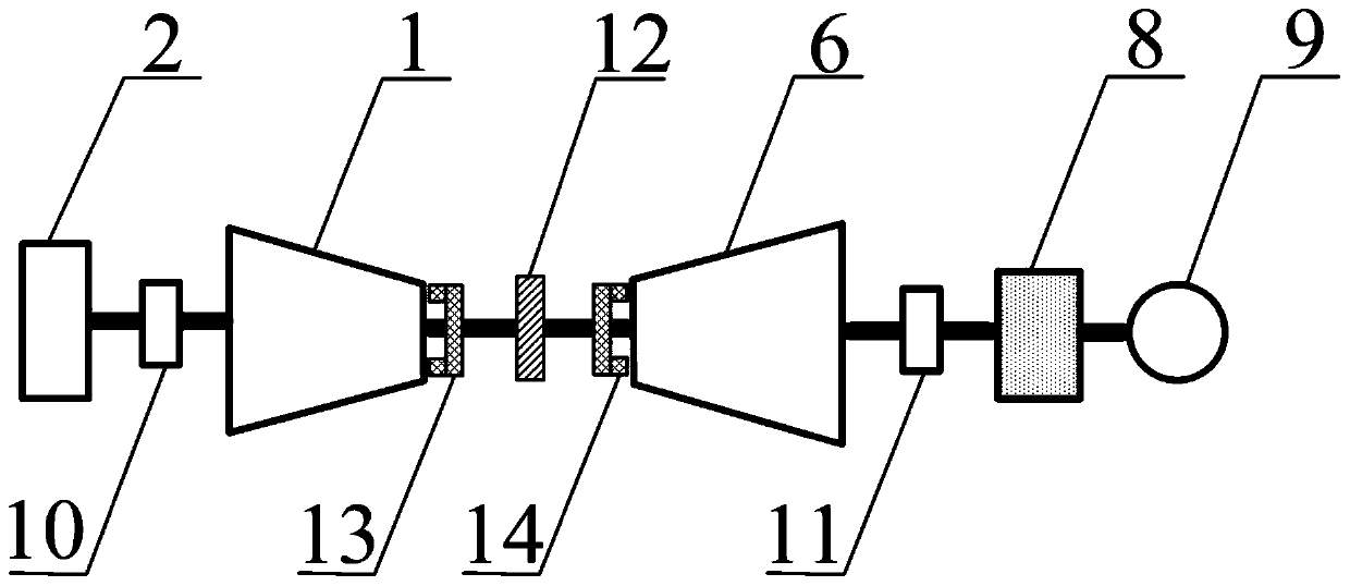
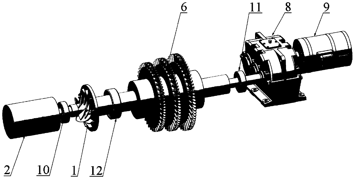
[0028] Such as Figure 1 to Figure 3 As shown, a supercritical carbon dioxide centrifugal compressor provided by the present invention has a coaxial structure with an axial flow turbine, including a centrifugal compressor 1, a high-speed starting motor 2, a surge tank 3, a regenerator 4, a heat source 5, an axial flow Turbine 6, cooler 7, gearbox 8, generator 9, compressor side radial bearing 10, turbine side radial bearing 11, thrust bearing 12, compressor side dry gas seal 13 and turbine side dry gas seal 14. Among them, the centrifugal compressor 1, the high-speed starter motor 2 and the axi...


PUM


Abstract

The invention discloses a coaxial structure of a supercritical carbon dioxide centrifugal compressor and an axial flow turbine. A high speed starting motor, the centrifugal compressor and the axial flow turbine are arranged on a main shaft from left to right in sequence and form the coaxial structure. The main shaft is connected with a rotating shaft of an electric generator through a gearbox. During working, the centrifugal compressor is started by the high speed starting motor, and carbon dioxide is compressed to a set high pressure by the centrifugal compressor, then the high pressure carbon dioxide flows through a buffer tank and enters a regenerator, and the high pressure carbon dioxide is preheated by adopting high temperature working mediums of an outlet of the axial flow turbine, then a heat source heats the high pressure carbon dioxide to a turbine outlet supercritical state, the high temperature high pressure carbon dioxide flows into the axial flow turbine to do work by expansion, internal energy of the carbon dioxide is transformed into mechanical energy, shaft work is supplied to the centrifugal compressor, and meanwhile, the mechanical energy is transmitted to the electric generator to generate electricity; and after the worked carbon dioxide flows through the regenerator, the carbon dioxide flows into a cooler finally, and the temperature is reduced to a needed state of an inlet of the centrifugal compressor.

Description

technical field [0001] The invention relates to an impeller mechanical power output structure, in particular to a coaxial structure of a supercritical carbon dioxide centrifugal compressor and an axial flow turbine. Background technique [0002] With the rapid development of science and technology, the demand for the performance of the power generation thermal system in the national economy and national defense technology is also getting higher and higher. It is difficult for the power generation system using conventional working fluid to meet the design requirements. The unique properties of carbon dioxide in the supercritical state make it one of the most promising natural working fluids. Carbon dioxide is colorless, odorless, non-toxic, and has good chemical stability. It exists widely in the atmosphere and is cheap and easy to obtain. Its critical temperature is 31.1°C and critical pressure is 7.4 MPa. It is relatively easy to achieve supercritical behavior and requires ...

Claims


Application Information

Patent Timeline
Patent Type & Authority Patents(China)
IPC IPC(8): F01K7/32F01D15/10F01D15/08
CPCF01D15/08F01D15/10F01K7/32
Inventor 谢永慧施东波张荻
Owner XI AN JIAOTONG UNIV
Why Eureka
Try Eureka