
Rotary table

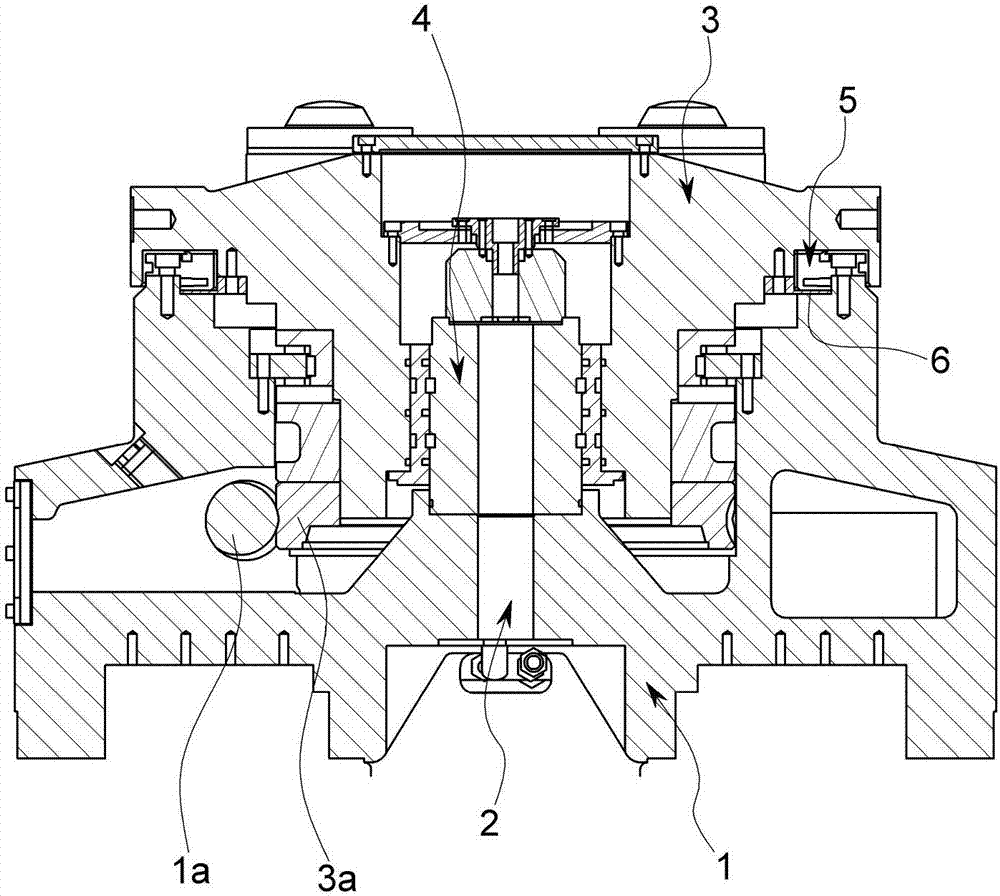
A technology of rotating workbench and workbench base, applied in the direction of manufacturing tools, rotary conveyors, metal processing equipment, etc., can solve the problem of damage to the connecting part 5d, and achieve the effect of improving durability

Active Publication Date: 2017-10-10
DN SOLUTIONS CO LTD
View PDF8 Cites 0 Cited by
  • Summary
  • Abstract
  • Description
  • Claims
  • Application Information

AI Technical Summary

Problems solved by technology

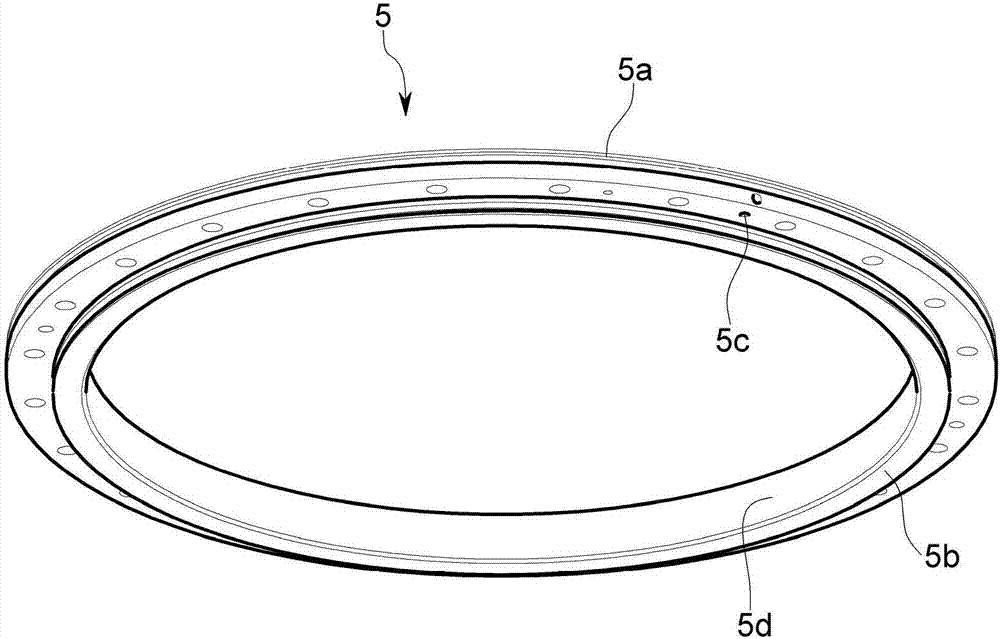
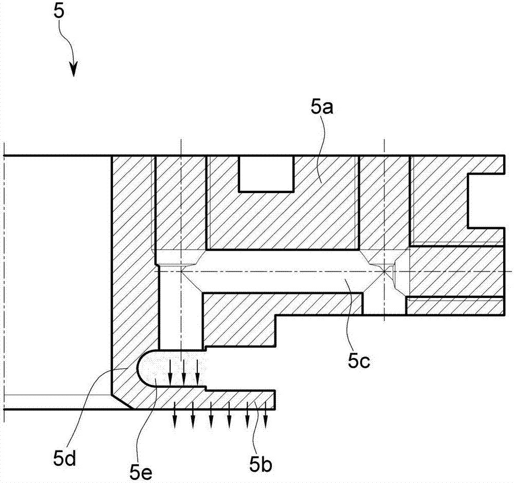
That is, there is a problem in the jig 5 that the connecting portion 5d is damaged due to the pressure formed in the chamber 5e.

Method used


Image

  • Rotary table
  • Rotary table
  • Rotary table

Examples


Embodiment Construction

[0059] Advantages and features of the present invention and methods for achieving them will become more apparent by referring to the accompanying drawings and embodiments described in detail to be described later.

[0060]Hereinafter, embodiments of the present invention will be described in detail with reference to the drawings. However, it should be understood that the present invention is not limited to the embodiments disclosed below, but can be realized in various ways. This embodiment is only used to improve the disclosure of the present invention, and the present invention may be different from the presently described embodiments. of various changes. However, in order to avoid obscuring the gist of the present invention, in some embodiments, detailed descriptions and specific illustrations thereof are omitted. In addition, the drawings are for understanding the present invention, and therefore are not shown in actual scale, and the size of some components may be shown ...


PUM


Abstract

A rotary table according to the exemplary embodiment of the present disclosure includes a piston 70 having a first tapered portion 72, and a clamp 80 having a second tapered portion 82. When the first tapered portion 72 comes into close contact with the second tapered portion 82 by a movement of the piston 70, a pallet base 30 is fixed to a table base 10, and thus the pallet base 30 is rotated, thereby maintaining a preset posture.

Description

technical field [0001] The invention relates to a rotary workbench, in particular to a rotary workbench in which a panel base can stop rotating at a specific position of the workbench base. Background technique [0002] Typically, a rotary table includes a clamping structure that allows the panel base to rotate on the table base and stops the rotation at a specific position. A panel can be loaded on the panel base, and a working object can be assembled on the panel. [0003] The machine tool performs cutting processing on the workpiece. In more detail, it is necessary to change the direction of the workpiece so that the cutting tool of the machine tool can approach the workpiece. That is, when the rotary table is operated, the panel and the panel base are rotated, and the workpiece is placed in a direction suitable for cutting. [0004] In addition, the rotational displacement of the rotary table can be numerically controlled by the servo motor, thereby obtaining fine ang...

Claims


Application Information

Patent Timeline
Patent Type & Authority Applications(China)
IPC IPC(8): B23Q1/52B23Q1/26
CPCB23Q1/26B23Q1/522B23Q16/10B23Q2220/004B23Q1/25B23Q16/08B23Q2701/02B23Q2716/06B23Q1/44B23Q16/026B23Q16/06B23Q16/083B65G29/00B65G47/8807
Inventor 金钟奉
Owner DN SOLUTIONS CO LTD
Learn More