
A Rolling Wing Vertical Take-off and Landing Multi-Perched Aircraft

A technology of vertical take-off and landing and rolling wings, which is applied to aircraft, rotary propellers, and vehicles that can be converted into airplanes. It can solve the problems of low payload and flight performance, small size, and bulky aircraft, and achieve multi-effectiveness. Effects of load and economy, good maneuverability and handling, and high aerodynamic efficiency

Active Publication Date: 2019-08-20
NANJING UNIV OF AERONAUTICS & ASTRONAUTICS
View PDF8 Cites 0 Cited by
  • Summary
  • Abstract
  • Description
  • Claims
  • Application Information

AI Technical Summary

Problems solved by technology

[0002] At present, there are many kinds of conceptual designs of flying cars in the world. According to the way of generating lift, the lift systems of flying cars mainly include fixed wings, autorotating rotors, driving rotors, vector engines and ducted fans. Among them, fixed wings or autorotating rotors For the lift system, the flying car needs a special runway to take off and land, does not have vertical take-off and landing capability, and has poor practicability (such as the first-generation flying car product TRANSITION designed by TERRAFUGIA in Massachusetts, USA and AEROMOBILE in Europe), so there is no Use practical value
Flying cars with rotating rotors or ducted fans as lift systems have the ability to take off and land vertically. Foreign countries have also studied vertical take-off and landing flying cars for many years, and have designed a variety of flying cars that can take off and land vertically, such as X-Hawk. It has better vertical take-off and landing functions, and has better concealment than helicopters, but its fuel consumption rate is 50% higher than that of helicopters. At the same time, because this aircraft is too heavy, its speed and range are not ideal, and It has problems with handling stability and is difficult to put into use
Due to the complex structural design, high cost, and low payload and flight performance of existing foreign flying cars, as an aircraft, it cannot be compared with general aviation aircraft; as a car, its structural design is not practical, easy to damage, and cannot meet the needs of automotive products. regulations
At present, many so-called "flying cars" can only be regarded as a special general aircraft (aircraft that can run on the ground), and cannot be called real flying cars.
[0003] At present, flying cars with vertical take-off and landing functions, whether using rotor or ducted fan technology, are either small in size and light in take-off weight, basically unable to load, and have no use value; The 2.5m vehicle width requirement limited by relevant regulations needs to provide a take-off site as a special equipment, and it cannot run on ordinary roads.
Moreover, they are all located on the left and right sides of the fuselage, using 2 to 4 or more rotors or ducted fans suspended on both sides of the foldable body as the power for take-off and flight. The lift surface and the power system are not on the same side. Multiple steering transmission systems are required, and the folding structure is too complicated and the weight cost is high. At the same time, there are relatively large requirements for the surrounding environment and area of ​​the vertical take-off and landing site, which seriously affects other normal running cars and is not suitable for driving on the ground. or when the road is congested

Method used


Image

  • A Rolling Wing Vertical Take-off and Landing Multi-Perched Aircraft
  • A Rolling Wing Vertical Take-off and Landing Multi-Perched Aircraft
  • A Rolling Wing Vertical Take-off and Landing Multi-Perched Aircraft

Examples


Embodiment Construction

[0026] The present invention provides a rolling wing vertical take-off and landing aircraft. In order to make the purpose of the present invention, technical solutions and effects clearer and clearer, the present invention will be further described in detail with reference to the accompanying drawings and examples. It should be understood that the specific implementations described here are only used to explain the present invention, not to limit the present invention.

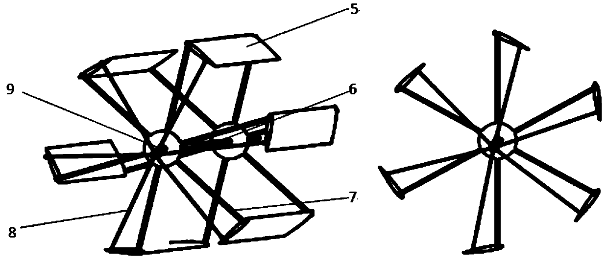
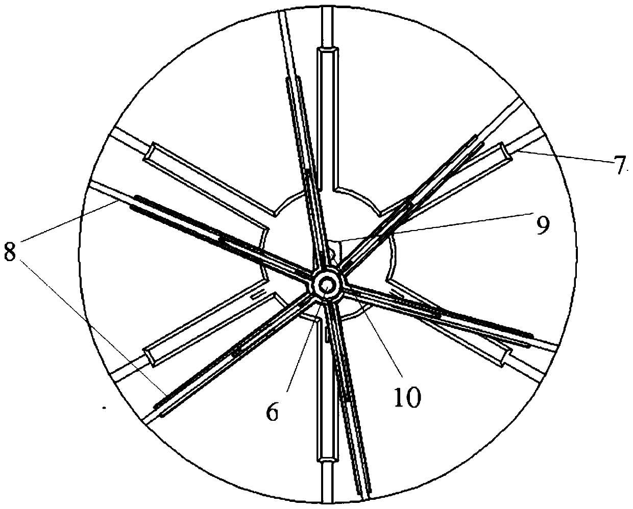
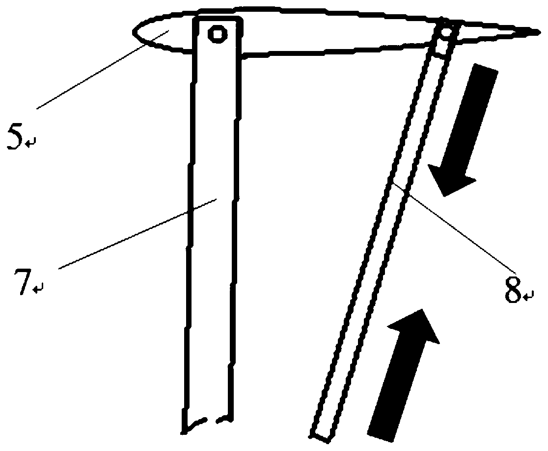
[0027] The rolling-wing vertical take-off and landing aircraft provided by the present invention comprises an aircraft body and several rolling-wing devices 2 connected to the aircraft body. Blades 5, blade brackets 7, variable From the connecting rod 8 and the biasing mechanism 9, the blade 5 is connected to the blade bracket 7, the blade bracket 7 is provided with a central shaft 10, and the biasing mechanism 9 is connected to the central shaft 10 , setting the offset amount for the offset mechanism 9, so th...


PUM


Abstract

The invention relates to a rolling-wing vertical takeoff and landing multi-dwelling aircraft. The rolling-wing vertical takeoff and landing multi-dwelling aircraft comprises a plurality of rolling wing devices, and is characterized in that blades, variable pitch connecting rods and offset mechanisms are arranged in each of the rolling wing devices; and offset quantity is set for the offset mechanisms so that the blades have an angle of attack at different rotation positions, a rotation state in which (adjustable) resultant force is always in a certain direction is formed, and eventually thrust in a certain direction is provided for the aircraft. The device is different from a rotor (or a propeller or a fan). The device rotates around a horizontal axis and can be coaxial with a wheel drive shaft, so that an air lifting system and a ground wheel propelling system are located in the same platform and can share a set of power devices and transmission systems; the rolling-wing vertical takeoff and landing multi-dwelling aircraft is compact in structure and light in weight; more effective payloads and economic benefits are brought to the aircraft; and the rolling-wing vertical takeoff and landing multi-dwelling aircraft can move forward by the reaction force produced when the rotation of the rolling wing devices agitates water in a water surface.

Description

technical field [0001] The invention relates to the field of water, land and air amphibious vehicles, in particular to a rolling wing vertical take-off and landing multi-habitat aircraft. Background technique [0002] At present, there are many kinds of conceptual designs of flying cars in the world. According to the way of generating lift, the lift systems of flying cars mainly include fixed wings, autorotating rotors, driving rotors, vector engines and ducted fans. Among them, fixed wings or autorotating rotors For the lift system, the flying car needs a special runway to take off and land, does not have vertical take-off and landing capability, and has poor practicability (such as the first-generation flying car product TRANSITION designed by TERRAFUGIA in Massachusetts, USA and AEROMOBILE in Europe), so there is no Use practical value. Flying cars with rotating rotors or ducted fans as lift systems have the ability to take off and land vertically. Foreign countries have...

Claims


Application Information

Patent Timeline
Patent Type & Authority Patents(China)
IPC IPC(8): B60F5/02B63H1/08B64C39/00
Inventor 朱清华冯旭碧申镇雷良招启军
Owner NANJING UNIV OF AERONAUTICS & ASTRONAUTICS
Learn More