Manufacturing technology of dual-layer carbon fiber tube with foam interlayer

A carbon fiber tube and foam layer technology, applied in the field of carbon fiber, can solve the problems of uneven thickness of glue, high noise and vibration of truss-type vehicles, and increased weight of carbon fiber tube, so as to avoid the problem of non-axis, reduce the subsequent work, glue Evenly distributed effect

Active Publication Date: 2017-10-03
上海瓴荣材料科技有限公司
View PDF5 Cites 0 Cited by
  • Summary
  • Abstract
  • Description
  • Claims
  • Application Information

AI Technical Summary

Problems solved by technology

In order to facilitate the connection, an assembly gap is often set between the carbon fiber tube and the joint, which leads to a large concentricity between the carbon fiber tube and the joint, and the thickness of the glue is uneven. If too much glue is applied, the excess glue will also It flows to the internal thread of the joint for connection, as well as the end face of the joint and the carbon fiber tube. After the glue is cured, it is very difficult to handle, resulting in an increase in the workload of post-processing
When the carbon fiber layer is bonded with glue, the joints are usually placed horizontally or vertically. Due to the influence of gravity, the glue will always be unevenly distributed, resulting in a decrease in the quality of the carbon fiber tube and the joint.
[0006] The existing carbon fiber tubes are all single-layer. Because the thickness of the carbon fiber cloth is small, the wall thickness of the carbon fiber tube is often small, and it has no attenuation effect on the noise and vibration of the car, which makes the noise and vibration of the truss car larger.
The bonding area between the carbon fiber cloth and the joint is also small, and in order to improve the bonding strength, it is often necessary to lengthen the boss of the joint to increase its contact area with the carbon fiber cloth, but this will lead to an increase in the weight of the carbon fiber tube

Method used


Image

  • Manufacturing technology of dual-layer carbon fiber tube with foam interlayer
  • Manufacturing technology of dual-layer carbon fiber tube with foam interlayer
  • Manufacturing technology of dual-layer carbon fiber tube with foam interlayer

Examples


Embodiment Construction

[0028] The words "upper", "lower" and "bottom" used herein are used for the convenience of explaining the structure of the present invention, and do not constitute any form of limitation to the content of the claims of the present invention.

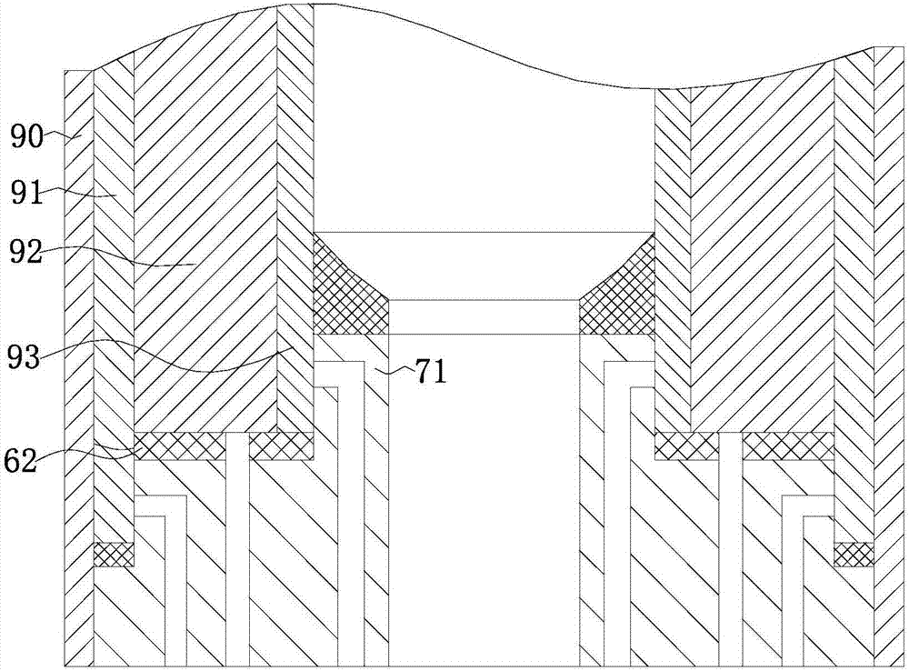
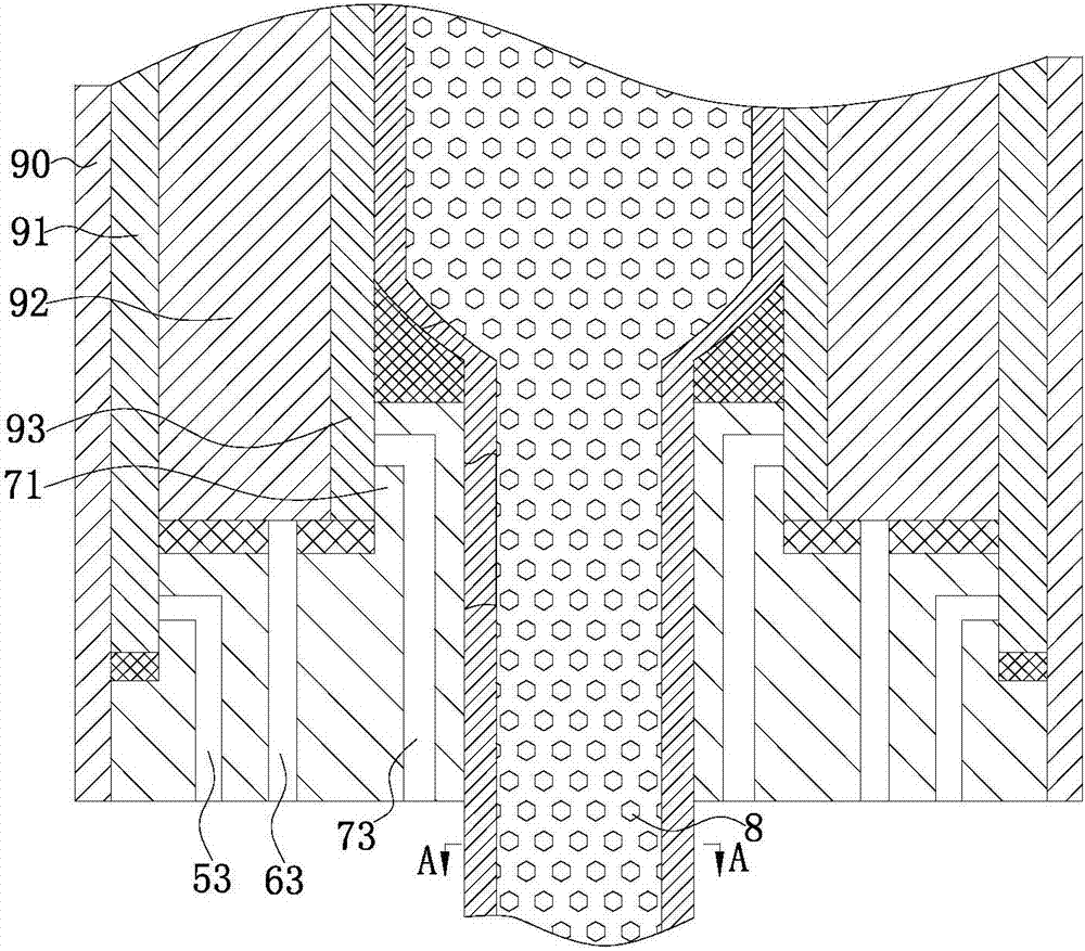
[0029] Such as Figure 1-Figure 8 Shown is a manufacturing process of a double-layer carbon fiber tube with a foam interlayer, wherein the double-layer carbon fiber tube is sequentially provided with an outer layer carbon fiber tube 1, a foam layer 2, and an inner layer carbon fiber tube 3 from the outside to the inside; the double-layer carbon fiber tube Both ends of the carbon fiber tube are respectively connected with a metal joint 4 .

[0030] Such as Figure 7 As shown, the metal joint 4 includes a first convex platform 51, a second convex platform 61 is arranged on the upper end surface of the first convex platform 51, and a third convex platform 71 is arranged on the upper end surface of the second convex platform 61; The upper ...


PUM


Abstract

The invention particularly relates to a manufacturing technology of a dual-layer carbon fiber tube with a foam interlayer. The dual-layer carbon fiber tube with the foam interlayer is rapid in forming and good in bonding quality. The manufacturing technology comprises following steps of inner die forming, carbon fiber tube forming and carbon fiber tube aftertreatment; the forming sted of the carbon fiber tube comprises inner layer carbon fiber tube forming, foam layer forming and outer layer carbon fiber tube forming; an inner carbon fiber tube body and an outer carbon fiber tube body are bonded with the foam layer to a certain degree, the bonding strength is improved, the foam layer absorbs vibration noise, all layers are bonded with a metal joint while being formed, the problem of disalignment of the carbon fiber tube and the joint after bonding is solved, in the bonding process, glue cannot flow in a joint inner hole, and the subsequent work is reduced; when the layers are bonded and formed, the layers are in the rotating state all the time, and glue in the bonding portion is more evenly distributed.

Description

[0001] This application is a divisional application for an invention patent with application number: 201610333315.7, application date: 2016-05-19, and the patent name "a double-layer carbon fiber tube with foam interlayer and its manufacturing process". technical field [0002] The invention relates to the field of carbon fibers, in particular to a manufacturing process of a double-layer carbon fiber tube with a foam interlayer. Background technique [0003] Carbon fiber composite materials have been gradually popularized from high-end fields such as aerospace to civilian fields. Carbon fiber tubes have the advantages of small specific gravity, high rigidity, high strength, and corrosion resistance, and are widely used in medical equipment and sports equipment. However, due to its own characteristics, the mechanical connection of carbon fiber tubes is extremely difficult, so the use of glue bonding has become a relatively simple and efficient connection method. Today, many s...

Claims


Application Information

Patent Timeline
Patent Type & Authority Applications(China)
IPC IPC(8): B29C65/48B62D21/08B32B9/00B32B9/04
CPCB29C65/48B32B9/007B32B9/046B62D21/08
Inventor 陈子龙
Owner 上海瓴荣材料科技有限公司
Why Eureka
Try Eureka