Concrete batching machine for concrete stirring station

A concrete and batching machine technology, which is applied in mixing plants, batching and batching equipment, clay preparation equipment, etc., can solve the problems of simple structure of concrete batching machine, affecting the quality of concrete, uneven mixing, etc., to prevent excessive load-bearing deformation and desoldering , prevent deformation and damage, and prolong the service life

Inactive Publication Date: 2017-10-03
黔西南州启腾矿山设备有限公司
View PDF8 Cites 1 Cited by
  • Summary
  • Abstract
  • Description
  • Claims
  • Application Information

AI Technical Summary

Problems solved by technology

[0003] At present, the concrete batching machines in concrete mixing plants have high measurement accuracy and distribution efficiency, but they are prone to layered accumulation of configured concrete ingredients, resulting in uneven mixing during processing, which affects the quality of concrete. Secondly, Some poor-quality concrete batching machines have simple structures, poor stability when used, and short service life

Method used


Image

  • Concrete batching machine for concrete stirring station
  • Concrete batching machine for concrete stirring station
  • Concrete batching machine for concrete stirring station

Examples


Embodiment 1

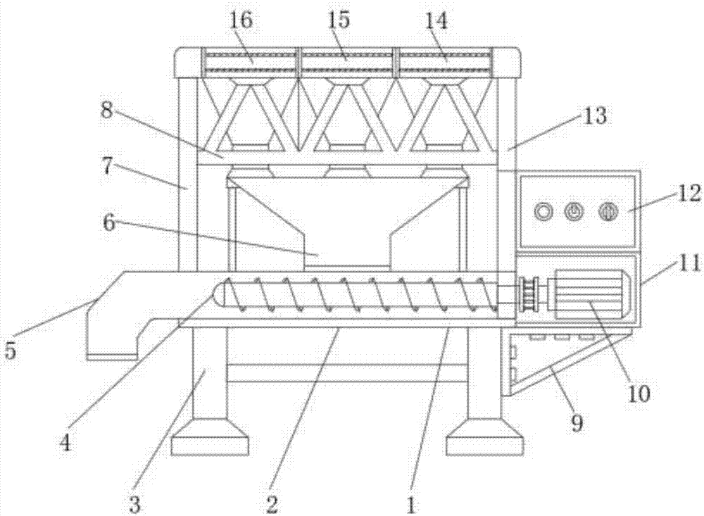
[0023] Embodiment one, with reference to Figure 1-4 , a concrete batching machine for a concrete batching plant, comprising a batching machine body 2, a feeding pipe 1 is welded on the batching machine body 2, and a discharge port 5 is welded at one end of the feeding pipe 1, and the batching machine body 2 is located on the feeding One side of the pipe 1 is screw-fixed with a motor box 11 through a tripod 9, and a feeding motor 10 is fixed inside the motor box 11, and the feeding motor 10 is connected to the screw feeding rod 4 inside the feeding pipe 3 through a transmission shaft. The electric control box 12 is fixed on the top of the motor box 11, the first support frame 7 and the second support frame 13 are welded symmetrically on both sides of the top of the batching machine body 2, and the first support frame 7 and the second support frame 3 are welded between the top One batching bin 14, the second batching bin 15 and the third batching bin 16, the bottom batching por...

Embodiment 2

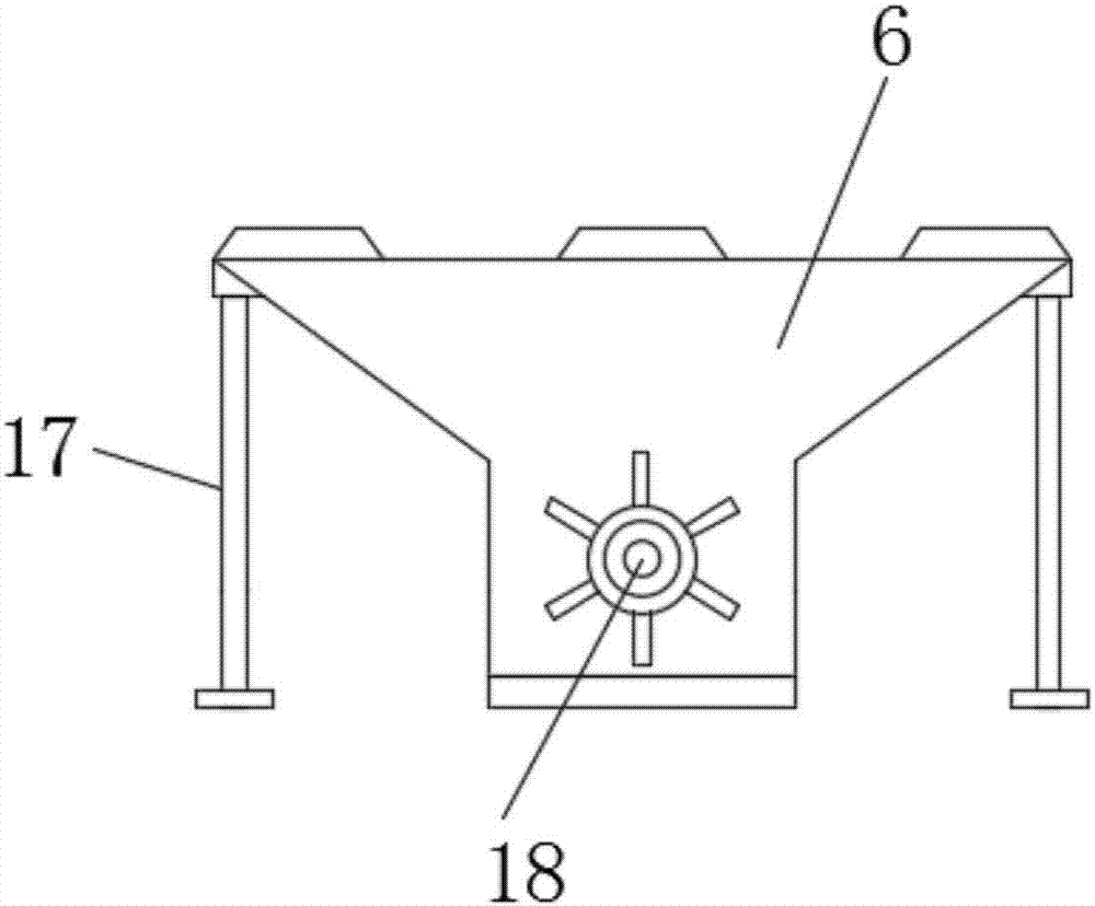
[0024] Embodiment two, refer to Figure 1-2 , the two sides of the mixing bin 6 are symmetrically welded with the auxiliary support 7 for auxiliary support of the mixing bin 6, the inner vertical center line of the mixing bin 6 is connected with the stirring shaft 18 through the rotating shaft, and the two auxiliary brackets 7 can be used for mixing. Auxiliary welding is performed on the material bin 6, so as to prevent the vibration generated during the operation of the equipment from causing the de-soldering of the mixing bin, and at the same time enhance the stability of the mixing bin.

Embodiment 3

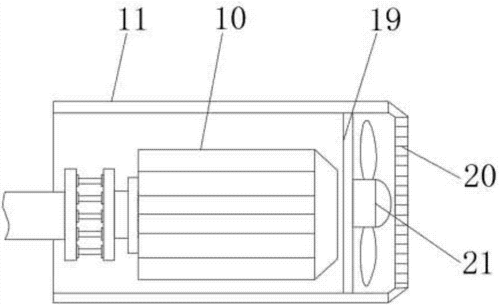
[0025] Embodiment three, refer to figure 1 and 3 , the inside of the motor box 11 is located on the outside of the feeding motor 10 and is welded with a heat dissipation fan 21 through the fan fixing frame 19, and a heat dissipation dust cover 20 is welded on the outer shell of the motor box 11, and the heat dissipation fan 21 can dissipate heat to the feeding motor 10, Prevent the feeding motor 10 from heating and prolong its service life.


PUM


Abstract

The invention discloses a concrete batching machine for a concrete stirring station. The concrete batching machine comprises a batching machine body; a conveying pipe is welded to the batching machine body, and a discharging outlet is welded to one end of the conveying pipe; a motor box is spirally fixed to the side, located on the conveying pipe, of the batching machine body through a tripod; a conveying motor is fixed into the motor box, and the conveying motor is in transmission connection with a spiral conveying rod inside the conveying pipe through a rotating shaft of the motor; and an electric control box is fixed to the top of the motor box. In the concrete batching machine, firstly a mixing bin is arranged, and a stirring rotating shaft is rotatably connected inside the mixing bin, so that ingredients in three batching bins enter the mixing bin simultaneously, then the stirring rotating shaft is automatically driven to rotate, thus the ingredients in the three batching bins are mixed, automatic mixing is achieved, and the situation that the prepared concrete ingredients are separated, thus the concrete ingredients are not uniform enough when being mixed and stirred, and the quality of concrete is affected is effectively prevented.

Description

technical field [0001] The invention relates to the technical field of concrete production and processing equipment, in particular to a concrete batching machine for a concrete mixing station. Background technique [0002] Concrete mixing plant is a combined device used to centrally mix concrete, also known as concrete prefabrication field. Because of its high degree of mechanization and automation, its productivity is also high, and it can ensure the quality of concrete and save cement. It is often used in large and medium-sized water conservancy, electric power, bridges and other projects with large concrete engineering volume, long construction period, and concentrated construction sites. With the development of municipal construction, the batching station that adopts centralized mixing and provides commercial concrete has great advantages, so it has been developed rapidly, and it has created conditions for the promotion of concrete pumping construction and the realizatio...

Claims


Application Information

Patent Timeline
Patent Type & Authority Applications(China)
IPC IPC(8): B28C7/04B28C7/06B28C7/10
CPCB28C7/0481B28C7/0404B28C7/067B28C7/10
Inventor 张超
Owner 黔西南州启腾矿山设备有限公司
Why Eureka
Try Eureka