
Device and method for testing ash accumulation characteristics of flue gas waste heat exchanger

A flue gas waste heat and heat exchanger technology, which is applied in the field of industrial waste heat recovery, can solve the problems of inconvenient disassembly and assembly and replacement of heat exchange tubes, and achieves the effect of reliable test results and overcoming human error.

Active Publication Date: 2017-09-29
XI AN JIAOTONG UNIV
View PDF6 Cites 17 Cited by
  • Summary
  • Abstract
  • Description
  • Claims
  • Application Information

AI Technical Summary

Problems solved by technology

[0004] The purpose of the present invention is to overcome the above-mentioned deficiencies in the prior art and provide a device and method for testing the ash accumulation characteristics of the flue gas waste heat heat exchanger, which does not need to disassemble the heat exchange tube to measure the ash accumulation Instead, by monitoring and calculating the decline trend and amount of the heat transfer coefficient over time of the heat exchanger at any time, calculating the fouling thermal resistance of the heat exchanger, and then evaluating the dust deposition characteristics of the heat exchange tubes, it overcomes the previous need The human error caused by the measurement of the weight of the accumulated dust, and the defects that the test device is installed inside the boiler, and it is inconvenient to disassemble and replace the heat exchange tube, etc.

Method used


Image

  • Device and method for testing ash accumulation characteristics of flue gas waste heat exchanger
  • Device and method for testing ash accumulation characteristics of flue gas waste heat exchanger
  • Device and method for testing ash accumulation characteristics of flue gas waste heat exchanger

Examples


Embodiment Construction

[0032] The specific implementation manners of the present invention will be described in detail below in conjunction with the drawings and embodiments.

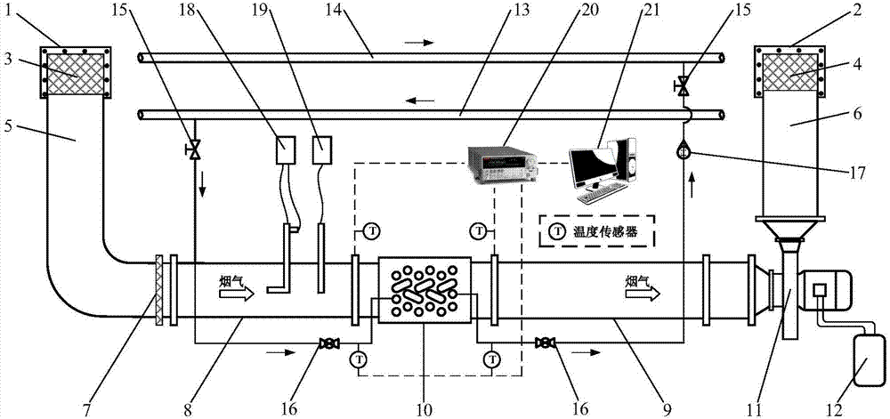
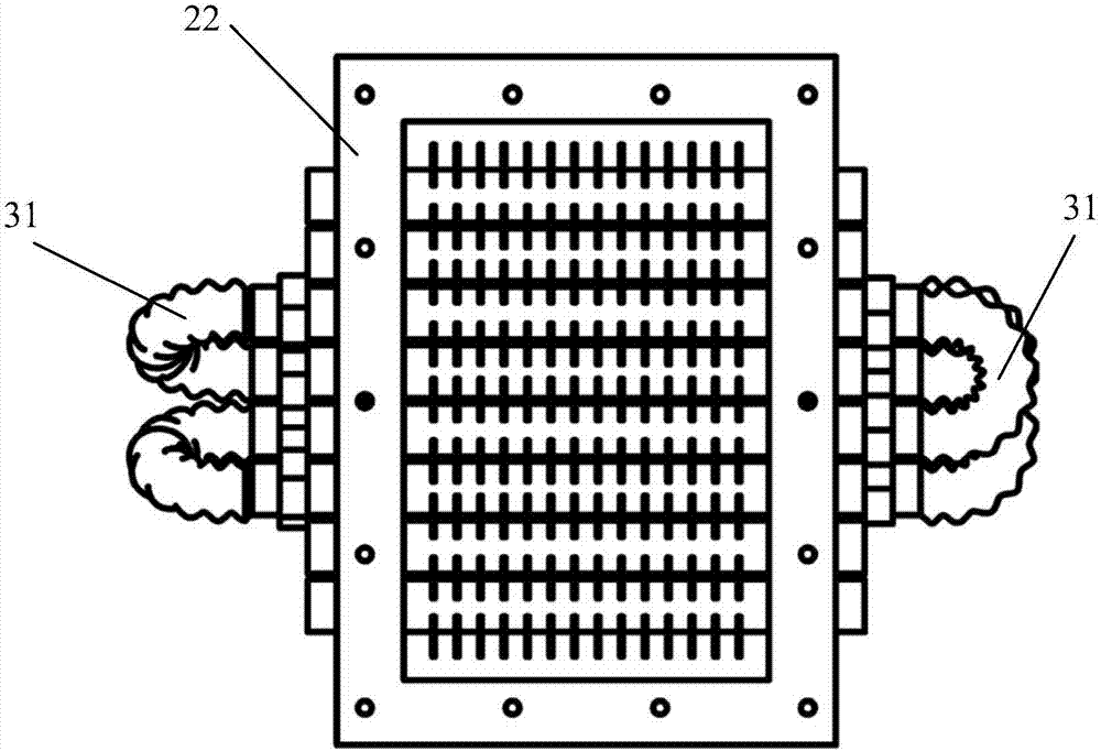
[0033] The present invention mainly utilizes the characteristic that the heat transfer coefficient will decrease when the surface of the heat exchange tubes accumulates dust, and calculates the heat transfer in real time by monitoring the flue gas temperature at the inlet and outlet of the heat exchanger in the test section and the water temperature at the inlet and outlet in real time. The decreasing trend and amount of the heat transfer coefficient of the heat exchanger over time are calculated to calculate the fouling thermal resistance of the heat exchanger, and then to evaluate the ash deposition characteristics of the heat exchange tube. The device of the present invention can be installed on the front side of the dust collector of the utility boiler or the heating boiler. In this example, the device system of the prese...


PUM


Abstract

A device and a method for testing ash deposition characteristics of a flue gas waste heat exchanger are disclosed, the device includes a test section heat exchanger, a flue gas circulation loop, a water circulation loop and a test system, and the flue gas circulation loop, the water circulation loop and the test system are respectively connected with the test section heat exchanger. Gas-side high temperature dust-containing flue gas of the test section heat exchanger in the flue gas circulation loop is led from a boiler, flows through the exchanger, and sent back to the boiler, water-side water supply of the test section heat exchanger in the a water circulation loop is directly from boiler water supply; the testing system can be used to calculate the fouling resistance of the test section heat exchanger by monitoring and calculating at any time the decrease trend and the declining quantity with time of heat transfer coefficient of the test section heat exchanger so as to evaluate the ash deposition characteristics of a heat exchanger tube. The types and the layout mode of testing tubes can be replaced freely without influence on the operation of the boiler, the testing method can be visualized, and monitoring of the ash deposition condition of a test section can be facilitated. The device overcomes human errors caused by measuring of the ash deposition weight in the prior art and the defects of the inconvenience of installation, dismounting and replacing, and the like of the heat exchange tube due to installation of the test device in the boiler.

Description

technical field [0001] The invention belongs to the field of industrial waste heat recovery, and in particular relates to a device and method for testing the ash accumulation characteristics of a flue gas waste heat heat exchanger. Background technique [0002] my country is a big energy consuming country. Industrial energy consumption accounts for the largest share in the proportion of energy consumption, accounting for more than 70% of the total energy consumption. At least 50% of it is converted into industrial waste heat with different carriers and different temperatures, most of which can be recycled. use. As the world continues to pay attention to energy issues and energy saving and emission reduction, heat exchangers are widely used in industrial processes for waste heat recovery and utilization of flue gas. Convective heat exchange is performed between the flue gas and the working medium of the heat exchange equipment, and its heat exchange performance has an importa...

Claims


Application Information

Patent Timeline
IPC IPC(8): G01N25/20
CPCG01N25/20
Inventor 何雅玲王飞龙汤松臻李明佳陶于兵赵钦新
Owner XI AN JIAOTONG UNIV
Learn More