
Method for adjusting engagement gap between balance shaft driven gear and crankshaft driving gear of engine

A gap adjustment method and driven gear technology, which is applied to belts/chains/gears, mechanical equipment, transmission parts, etc., can solve the problems of poor assembly effect and low assembly efficiency, reduce adjustment time and improve work efficiency Effect

Active Publication Date: 2017-09-29
CHONGQING CHANGAN AUTOMOBILE CO LTD
View PDF7 Cites 2 Cited by
  • Summary
  • Abstract
  • Description
  • Claims
  • Application Information

AI Technical Summary

Problems solved by technology

Therefore, during the assembly process of the double balance shaft, it is necessary to repeatedly detect and adjust the tooth side clearance at the meshing position of the gears to meet the assembly requirements, the assembly efficiency is extremely low, and the assembly effect is not good

Method used


Image

  • Method for adjusting engagement gap between balance shaft driven gear and crankshaft driving gear of engine
  • Method for adjusting engagement gap between balance shaft driven gear and crankshaft driving gear of engine
  • Method for adjusting engagement gap between balance shaft driven gear and crankshaft driving gear of engine

Examples


Embodiment Construction

[0029] The present invention will be further described below in conjunction with the accompanying drawings.

[0030] The method for adjusting the tooth side clearance of the meshing gear of the engine balance shaft according to the present invention comprises the following steps:

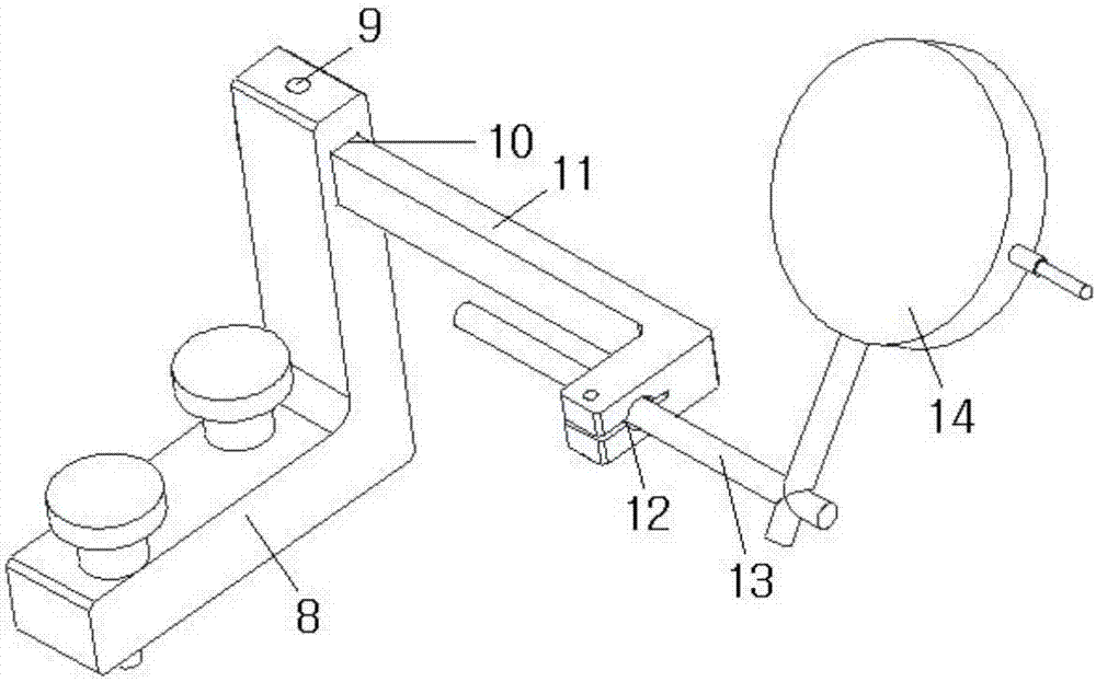
[0031] Step 1, preparing a crankshaft rotation device, a crankshaft rotation angle control device, a balance shaft gap measurement device and a balance shaft timing positioning device. The crankshaft rotating device such as figure 1 As shown, it includes a fixed plate 1 and a scale plate 2 stacked together, a positioning pin 5 is arranged on the inner side of the fixed plate 1, and an angle scale line is marked on the outer edge of the scale plate 2 . The crankshaft rotation angle control device such as figure 2 As shown, the pointer 7 and the pointer holder 6 are included, and the pointer 7 is horizontally fixed on the pointer holder 6 . The balance shaft gap measuring device is as image 3 A...


PUM


Abstract

The invention discloses a method for adjusting an engagement gap between a balance shaft driven gear and a crankshaft driving gear of an engine. A technology gasket is mounted between the joint positions of a balance shaft fixing cover and an engine box body in a cushioned mode; a fixing disc of a crankshaft rotating device is mounted and fixed to the end portion of a crankshaft; a joint head of a balance shaft timing positioning device is mounted on the end portion of a second balance shaft in a sleeving mode; a supporting base of a balance shaft gap measuring device is fixed to the top face of an engine box body; the crankshaft is rotated, and the difference valve of the maximum value and the minimum value displayed on a dial indicator is read and recorded; the difference value between the real central distance and the non-backlash central distance of a driving gear and a second driven gear is calculated according to the engagement equation of a parallel cylinder gear; the thickness of a needed gasket which is mounted between the balance shaft fixing cover and the engine box body in a cushioned mode is determined; and finally the technology gasket is replaced by the gasket with the calculated thickness. The method can rapidly and accurately adjust the backlash value at the engagement position of the driven gear on the balance shaft and the driving gear on the crankshaft.

Description

technical field [0001] The invention belongs to a method for installing automobile engine components, in particular to a method for adjusting the meshing tooth side clearance between a driven gear of an engine balance shaft and a drive gear of a crankshaft. Background technique [0002] When the automobile engine is in working condition, the piston has a large inertial force in the cylinder, and the inertial force is unbalanced, which easily causes the engine to vibrate. In order to eliminate or reduce this kind of vibration, dual balance shafts are usually installed on the automobile engine, and the unbalance of the dual balance shafts is used to offset the second-order reciprocating inertial force generated during the operation of the engine. The specific structure is as follows: Figure 7 and Figure 8 As shown, a drive gear 26 is installed on the crankshaft 23 in the engine case 22, and the first balance shaft 24 and the second balance shaft 25 are installed on the top s...

Claims


Application Information

Patent Timeline
Patent Type & Authority Applications(China)
IPC IPC(8): F16H57/12
CPCF16H57/12
Inventor 撒利军薛生梅王攀
Owner CHONGQING CHANGAN AUTOMOBILE CO LTD
Learn More