Offset connection fixing structure of center lines of plate springs and center lines of lower wing surfaces of longitudinal beams

A technology for fixing structures and longitudinal beams, which is applied in the direction of springs, leaf springs, vehicle springs, etc., can solve problems such as the short distance between the battery pack and the leaf spring pin mounting bolts, and does not meet the assembly clearance, so as to increase the center distance of leaf springs, Reasonable design and simple structure

Inactive Publication Date: 2019-09-24
北京华田汽车科技有限公司
View PDF5 Cites 0 Cited by
  • Summary
  • Abstract
  • Description
  • Claims
  • Application Information

AI Technical Summary

Problems solved by technology

For the chassis layout plan using standard battery packs and mid-mounted battery systems, the center distance between the existing leaf springs makes the distance between the battery pack and the mounting bolts of the leaf spring pins very close, which does not meet the assembly clearance requirements

Method used


Image

  • Offset connection fixing structure of center lines of plate springs and center lines of lower wing surfaces of longitudinal beams
  • Offset connection fixing structure of center lines of plate springs and center lines of lower wing surfaces of longitudinal beams
  • Offset connection fixing structure of center lines of plate springs and center lines of lower wing surfaces of longitudinal beams

Examples


Embodiment Construction

[0016] See attached picture.

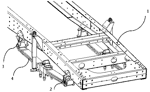
[0017] figure 1 It is a schematic diagram of the scheme. It can be seen from the figure that the front leaf spring is installed on the chassis longitudinal beam through the front and rear two lifting lugs, and the front axle is connected to the leaf spring through saddle bolts and shock pads.

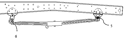
[0018] figure 2 It is the side view of the plan. It can be seen from the figure that the front lifting ear is fixed with the leaf spring through a pin, and here is an immovable dead point; the rear lifting ear is fixed with the leaf spring through a pin. is an active point that can be moved.

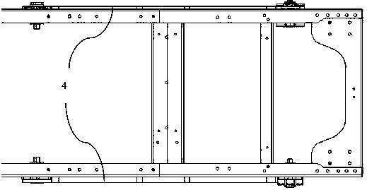
[0019] image 3 It is a top view of the plan. It can be seen from the figure that the leaf spring is covered under the lower wing surface, and the coverage size can be adjusted according to the needs of the whole vehicle.

[0020] Figure 4 It is a schematic diagram of the front and rear lifting lugs. It can be seen from the figure that the front lifting lug is...


PUM


Abstract

The invention discloses an offset connection fixing structure of center lines of plate springs and center lines of lower wing surfaces of longitudinal beams. The offset connection fixing structure is characterized in that the plate springs have the center lines in the longitudinal direction of a vehicle, and the plate springs are each roughly and equally divided into two parts by the center lines; and the lower wing surfaces of the longitudinal beams have the center lines in the longitudinal direction of the vehicle, and the lower wing surfaces of the longitudinal beams are each roughly and equally divided into two parts by the center lines; front lifting lugs and rear lifting lugs are partially connected in an overlapped mode on the horizontal plane, and the center lines of the plate springs and the center lines of the longitudinal beams are fixed together in an offset mode; and the front lifting lugs and the rear lifting lugs are in an h shape and in an L shape, so that the plate springs are partially covered under the lower wing surfaces of the longitudinal beams, and the front lifting lugs and the rear lifting lugs of the plate springs are fixed to the longitudinal beams of a chassis and are connected with plate spring elastic pieces. The offset connection fixing structure of the center lines of the plate springs and the center lines of the lower wing surfaces of the longitudinal beams has the advantages that the structure is simple, the design is reasonable, the center distance of the plate springs is increased by changing the form of the lifting lugs of the plate springs, the lifting lugs of the plate springs can adjust the size covered under the lower wing surfaces of the longitudinal beams according to the requirements of a whole vehicle, and thus the spacing of the plate springs can meet the clearance requirements of an arrangement scheme of a middle-mounted chassis in a standard battery system.

Description

technical field [0001] The invention relates to the technical field of electric vehicles, in particular to a suspension system suitable for electric vehicles. Background technique [0002] At present, the front leaf spring of the pure electric special vehicle is completely covered under the lower wing surface of the longitudinal beam, and the leaf spring lug matches it. For the chassis layout plan using standard battery packs and mid-mounted battery systems, the center distance of the existing leaf springs makes the distance between the battery pack and the mounting bolts of the leaf spring pins very close, which does not meet the assembly clearance requirements. Contents of the invention [0003] The object of the present invention is to provide a structure for offset connection and fixing of the centerline of the leaf spring and the centerline of the lower airfoil of the longitudinal beam. [0004] The present invention is achieved through the following technical soluti...

Claims


Application Information

Patent Timeline
IPC IPC(8): B60G11/10
CPCB60G11/10B60G2202/112B60G2204/121B60G2300/50
Inventor 贺林延浩关庆生
Owner 北京华田汽车科技有限公司
Why Eureka
Try Eureka