Eureka AIR delivers breakthrough ideas for toughest innovation challenges, trusted by R&D personnel around the world.

Shield tunneling machine cutter capable of being quickly replaced

A shield machine and cutting tool technology, which is applied in mining equipment, earthwork drilling, tunnels, etc., can solve problems that affect work efficiency, serious tool wear, and dangers caused by manual excavation of tunnels, etc., and achieve the effect of fixed tools and cost saving

Pending Publication Date: 2017-09-29
薛飞
View PDF0 Cites 9 Cited by
  • Summary
  • Abstract
  • Description
  • Claims
  • Application Information

AI Technical Summary

Problems solved by technology

[0002] The shield machine is a special construction machine for tunneling, mostly used in subways, tunnels, and pipelines. The shield machine has a high degree of automation, saves manpower, and has a fast construction speed. Manual excavation of tunnels is prone to danger. The use of the shield machine depends on the cutter head. The tool is used to excavate the soil. During the underground excavation, the tool often encounters hard stones, scrap iron, etc., so the tool must be fixed to prevent the tool from shaking and affect the work effect, and the tool is seriously worn underground. The service life is short, if it is inconvenient to change the tool, it will affect the work efficiency

Method used


Image

  • Shield tunneling machine cutter capable of being quickly replaced
  • Shield tunneling machine cutter capable of being quickly replaced
  • Shield tunneling machine cutter capable of being quickly replaced

Examples


Embodiment 1

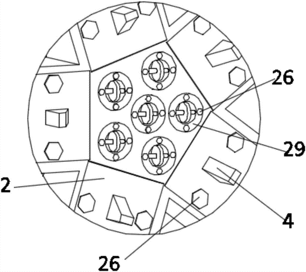
[0028] see Figure 1-6 , the present invention provides a technical solution: a quick-change shield machine tool, including a cutter head 1, the cutter head 1 is fixedly connected to a plurality of tool holders 2 in the circumferential direction, and the tool holder 2 is provided with a tool hole 3, a first cutter 4 is movably connected in the cutter hole 3, and the first cutter 4 includes a handle 41 and a cutter head 42, and the cutter head 42 and the handle 41 are fixedly connected, and the bottom of the handle 41 There are first grooves 7 on both sides, and a fixed plate 8 is movably connected in the first grooves 7. After the first cutter 4 is inserted into the cutter hole 3, the first groove 7 is just located in the first cavity 9 , and then make the fixing plate 8 snap into the first groove 7, the first tool 4 can be fixed, the fixing plate 8 is slidably connected in the first cavity 9, and the bottom surface of one end of the fixing plate 8 is fixedly connected with te...

Embodiment 2

[0031] see Figure 1-8, the present invention provides a technical solution: a quick-change shield machine tool, including a cutter head 1, the cutter head 1 is fixedly connected to a plurality of tool holders 2 in the circumferential direction, and the tool holder 2 is provided with a tool hole 3, a first cutter 4 is movably connected in the cutter hole 3, and the first cutter 4 includes a handle 41 and a cutter head 42, and both sides of the bottom of the handle 41 are provided with first grooves 7, so The first groove 7 is movably connected with a fixed plate 8. After the first tool 4 is inserted into the tool hole 3, the first groove 7 is just located in the first cavity 9, and then the fixed plate 8 is snapped into the first groove. 7, the first tool 4 can be fixed, the fixed plate 8 is slidably connected in the first cavity 9, the bottom surface of one end of the fixed plate 8 is fixedly connected with teeth 10, and the teeth 10 are connected with the first gear 11, the...

Embodiment 3

[0034] see Figure 9 , the present invention provides a technical solution: a quick-change cutter for shield machine, including a first cutter 4, the first cutter 4 includes a handle 41 and a cutter head 42, and the handle 41 is provided with a through hole Slot 32, the cutter head 42 is movably connected in the through groove 32, the bottom of the cutter head 42 is fixedly connected to the limit block 33, the limit block 33 is stuck in the through groove 32, and the limit block 33 is movably connected and fixed Block 34, the fixed block 34 and the limit block 33 are fixed on the handle 41 by bolts 26. After the first tool 4 is removed from the tool holder 2, the bolt 26 at the bottom of the handle 41 is unscrewed to remove the fixed Block 34 just can take out cutter head 42 in the through groove 32 of handle of a knife 41 then, and this is in order to prevent that cutter head 42 is damaged and handle of a knife 41 is intact in order to prevent first cutter 4 from occurring, a...


PUM


Abstract

The invention discloses a shield tunneling machine cutter capable of being quickly replaced. The shield tunneling machine cutter capable of being quickly replaced comprises a cutter disc, wherein cutter frames are fixed on the cutter disc, and each cutter frame is provided with first cutters; the bottom of each cutter handle is provided with two first grooves, and each first groove is internally provided with a fixing plate; a cog is meshed with a first gear, and a first rotary shaft drives a second gear through a transmission belt; the second gear is meshed with a third gear fixedly connected with a fourth gear, and the fourth gear is meshed with the cog on the fixing plate; one end of each second rotary shaft extends into a second groove, and the upper surface of each cutter frame is provided with pads provided with bolts which pass through the pads and the fixing plates and are fixedly connected to one cutter frame. According to the shield tunneling machine cutter capable of being quickly replaced, the cutters are clamped through the fixing plates and the pads and fastened with the bolts, the cutter frames are circumferentially distributed on the cutter disc, and therefore the number of the needed cutter frames can be selected based on demands; besides, the cutter handles and bits of the first cutters can be detachably replaced, so that the cost is saved; each pad is provided with a third groove, so that collision of the pads can be avoided when the cutters are in use, and the cutters can be fixed more tightly.

Description

technical field [0001] The invention relates to the technical field of shield machines, in particular to a quick-change cutter for shield machines. Background technique [0002] The shield machine is a special construction machine for tunneling, mostly used in subways, tunnels, and pipelines. The shield machine has a high degree of automation, saves manpower, and has a fast construction speed. Manual excavation of tunnels is prone to danger. The use of the shield machine depends on the cutter head. The tool is used to excavate the soil. During the underground excavation, the tool often encounters hard stones, scrap iron, etc., so the tool must be fixed to prevent the tool from shaking and affect the work effect, and the tool is seriously worn underground. The service life is short, and if it is inconvenient to change the tool, it will affect the work efficiency. Contents of the invention [0003] The purpose of the present invention is to provide a quick-change shield mac...

Claims


Application Information

Patent Timeline
Patent Type & Authority Applications(China)
IPC IPC(8): E21D9/087
CPCE21D9/0879
Inventor 薛飞
Owner 薛飞
Why Eureka
Eureka Blog
Learn More