
Turn-milling combined-type drilling and tapping center

A compound, turning-milling technology, applied to other manufacturing equipment/tools, manufacturing tools, etc., can solve the problem of single completion of drilling, milling, tapping, etc., to simplify workpiece clamping, meet production process requirements, and save non-production the effect of time

Pending Publication Date: 2017-09-29
GUANGDONG HARVEST START TECH CO LTD
View PDF8 Cites 6 Cited by
  • Summary
  • Abstract
  • Description
  • Claims
  • Application Information

AI Technical Summary

Problems solved by technology

[0004] Based on this, it is necessary to provide a turning-milling compound drilling and tapping center for the problem that ordinary drilling and tapping centers can only complete drilling, milling, and tapping.

Method used


Image

  • Turn-milling combined-type drilling and tapping center
  • Turn-milling combined-type drilling and tapping center

Examples


Embodiment 1

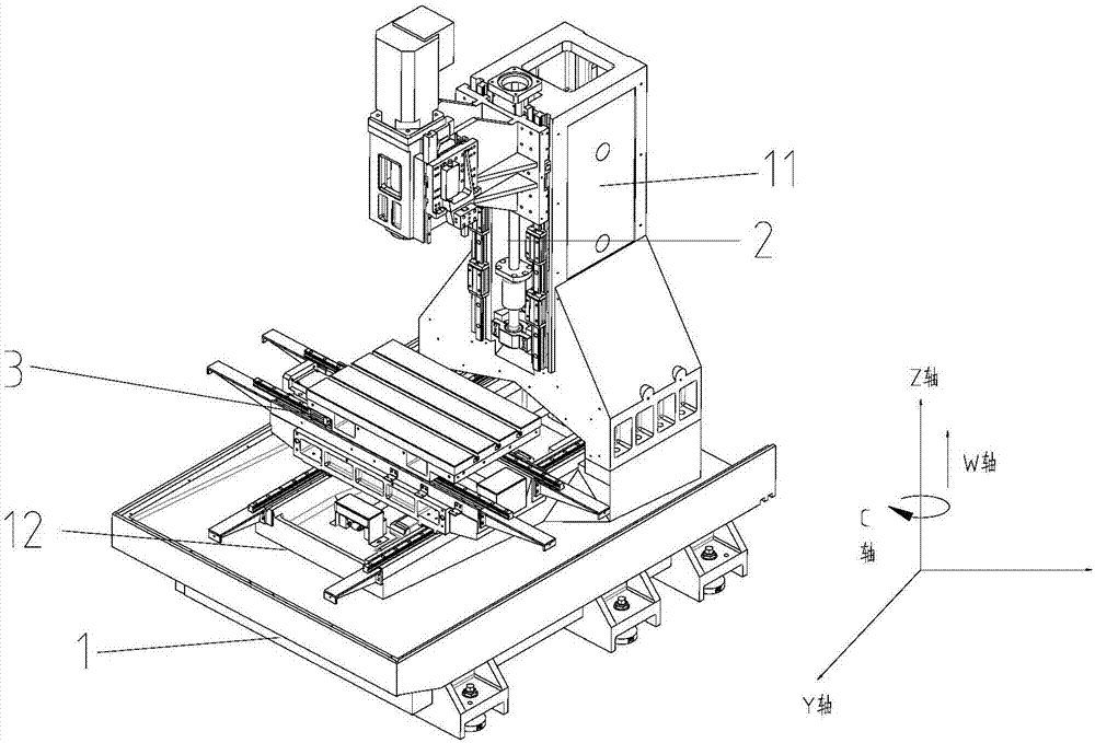
[0017] figure 1 It is a schematic structural diagram of a turning-milling compound drilling and tapping center according to an embodiment. Such as figure 1 As shown, a turning-milling compound drilling and tapping center includes: a milling machine tool 1, a turning head 2 and a turning-milling turntable 3; the turning head 2 is installed on the side of the milling head of the milling machine tool 1; the turning-milling turntable 3 is installed Above the worktable of the milling machine tool 1; the motion axes of the turning-milling compound drilling and tapping center are X axis, Y axis, Z axis, C axis, and W axis, wherein X, Y, and Z axes form a three-dimensional space, and the W axis Parallel to the Z axis, the W axis is the direction axis of the vertical feed movement of the turning head 2, the C axis rotates around the Z axis, and the C axis is the rotation direction axis of the turning and milling turntable 3; when the turning head 2 moves, the turning and milling turnt...

Embodiment 2

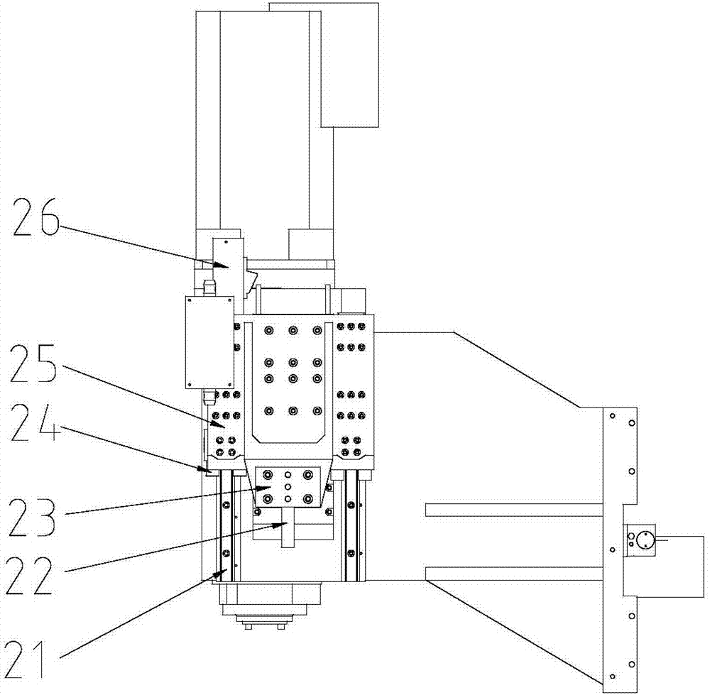
[0021] figure 1 It is a schematic structural diagram of a turning-milling compound drilling and tapping center according to an embodiment. figure 2 It is a schematic structural diagram of the turning head of the turning-milling compound drilling and tapping center of an embodiment. combine figure 1 with figure 2 This embodiment will be described.

[0022] A turning-milling compound drilling and tapping center, comprising: a milling machine tool 1, a turning head 2, and a turning-milling turntable 3; the turning head 2 is installed on the side of the milling head of the milling machine tool 1; the turning-milling turntable 3 is installed on the milling machine tool 1 above the worktable; the movement axes of the turning-milling compound drilling and tapping center are X-axis, Y-axis, Z-axis, C-axis, and W-axis, wherein X, Y, and Z-axes form a three-dimensional space, and W-axis and Z-axis Parallel, the W axis is the direction axis of the vertical feed movement of the turn...


PUM


Abstract

The invention relates to a turn-milling combined-type drilling and tapping center which comprises a milling machine tool, a turning head and a turn-milling rotary table; the turning head is installed on the side face of a milling head of the milling machine tool, and the turn-milling rotary table is installed on the surface of a workbench of the milling machine tool; the movement axes of the turn-milling combined-type drilling and tapping center are the X axis, the Y axis, the Z axis, the C axis and the W axis, and the W axis is in parallel with the Z axis; the X axis is the directional axis of perpendicular feeding movement of the turning head, the C axis rotates around the Z axis and is the rotary directional axis of the turn-milling rotary table; when the turning head moves, the turn-milling rotary table rotates at the preset rotary speed and the preset torque, the turning function is started, and the milling function is stopped; when the milling head moves, the turn-milling rotary table serves as a milling workbench, the milling function is started, and the turning function is stopped; a part is machined through cooperation of turning and milling, through one-time clamping, the working procedures such as turning, milling, drilling and tapping can be completed, machining of the overall complex part is completed, the machining precision is high, the economic and practical effects are achieved, and the production efficiency of a product is greatly improved.

Description

technical field [0001] The invention relates to the technical field of mechanical processing equipment, in particular to a turning-milling compound drilling and tapping center. Background technique [0002] Drilling and tapping center is a kind of CNC drilling and tapping center for cutting metal. It is also commonly called "drilling and milling tapping center", "drilling and tapping center", "drilling and milling center", "drilling and milling machining center" and so on. It is the fastest and high-precision drilling and tapping center integrating cutting, drilling and tapping in the market. It is derived from the traditional metal cutting drilling center-vertical machining center (computer gong). Compared with the traditional vertical machining center, the floor space and processing stroke are smaller. It is mainly used for processing light and small metals, and is not suitable for heavy cutting. The configuration usually adopts jig arm tool magazine or servo tool magazi...

Claims


Application Information

Patent Timeline
Patent Type & Authority Applications(China)
IPC IPC(8): B23P23/02
CPCB23P23/02
Inventor 祝烽李虹
Owner GUANGDONG HARVEST START TECH CO LTD
Learn More