Floor brushes and vacuum cleaners

A vacuum cleaner and suction port technology, applied in the direction of suction nozzles, etc., can solve the problems of increasing maintenance difficulty, processing complexity, increasing parts and components, etc., and achieve the effects of low production and maintenance costs, high dust removal efficiency, and reasonable location.

Active Publication Date: 2019-07-19
SUZHOU VACS ELECTRICAL
View PDF7 Cites 0 Cited by
  • Summary
  • Abstract
  • Description
  • Claims
  • Application Information

AI Technical Summary

Problems solved by technology

Although this patent document overcomes the above-mentioned defects, this structure is relatively complicated. Compared with the existing technology, parts are added, which increases the cost, also leads to the complexity of processing, and increases the difficulty of maintenance.

Method used


Image

  • Floor brushes and vacuum cleaners
  • Floor brushes and vacuum cleaners
  • Floor brushes and vacuum cleaners

Examples


Embodiment Construction

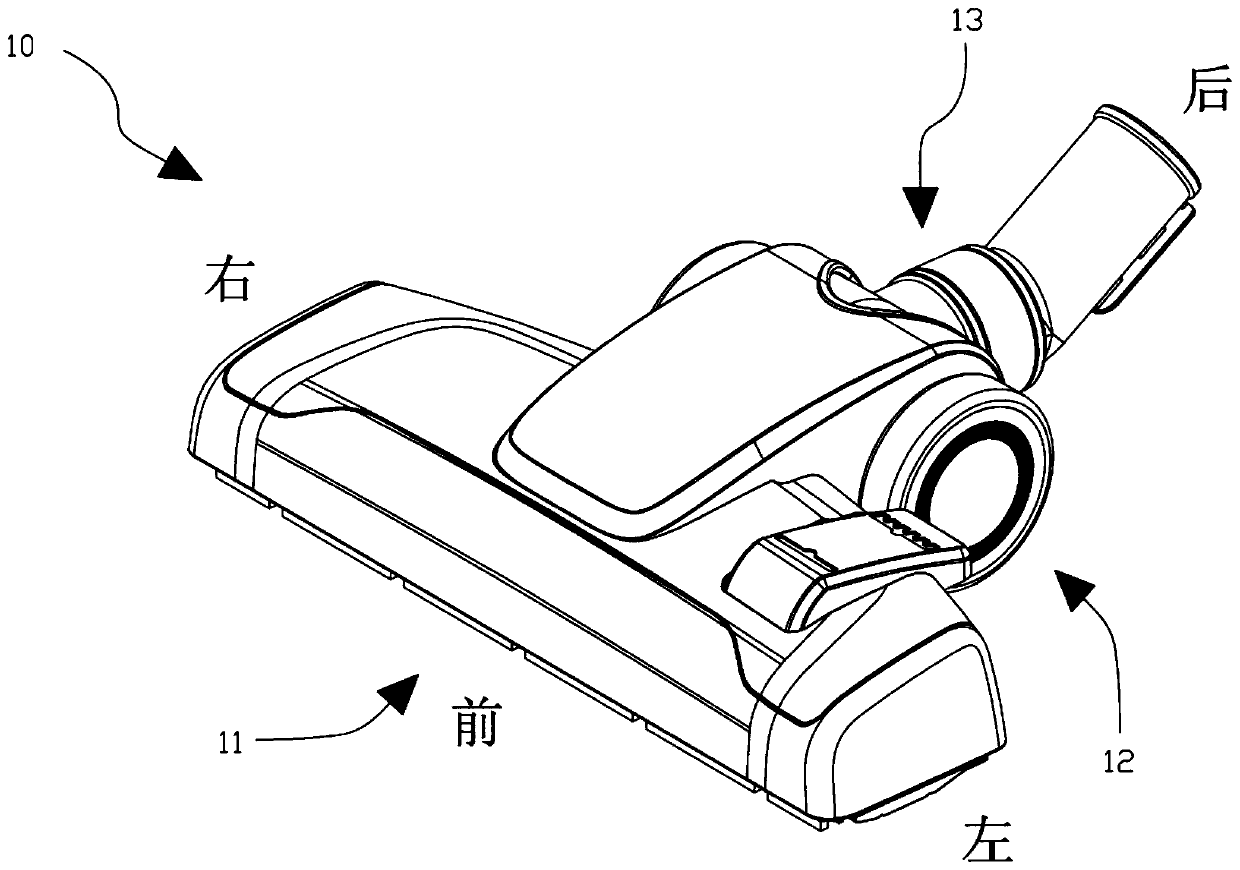
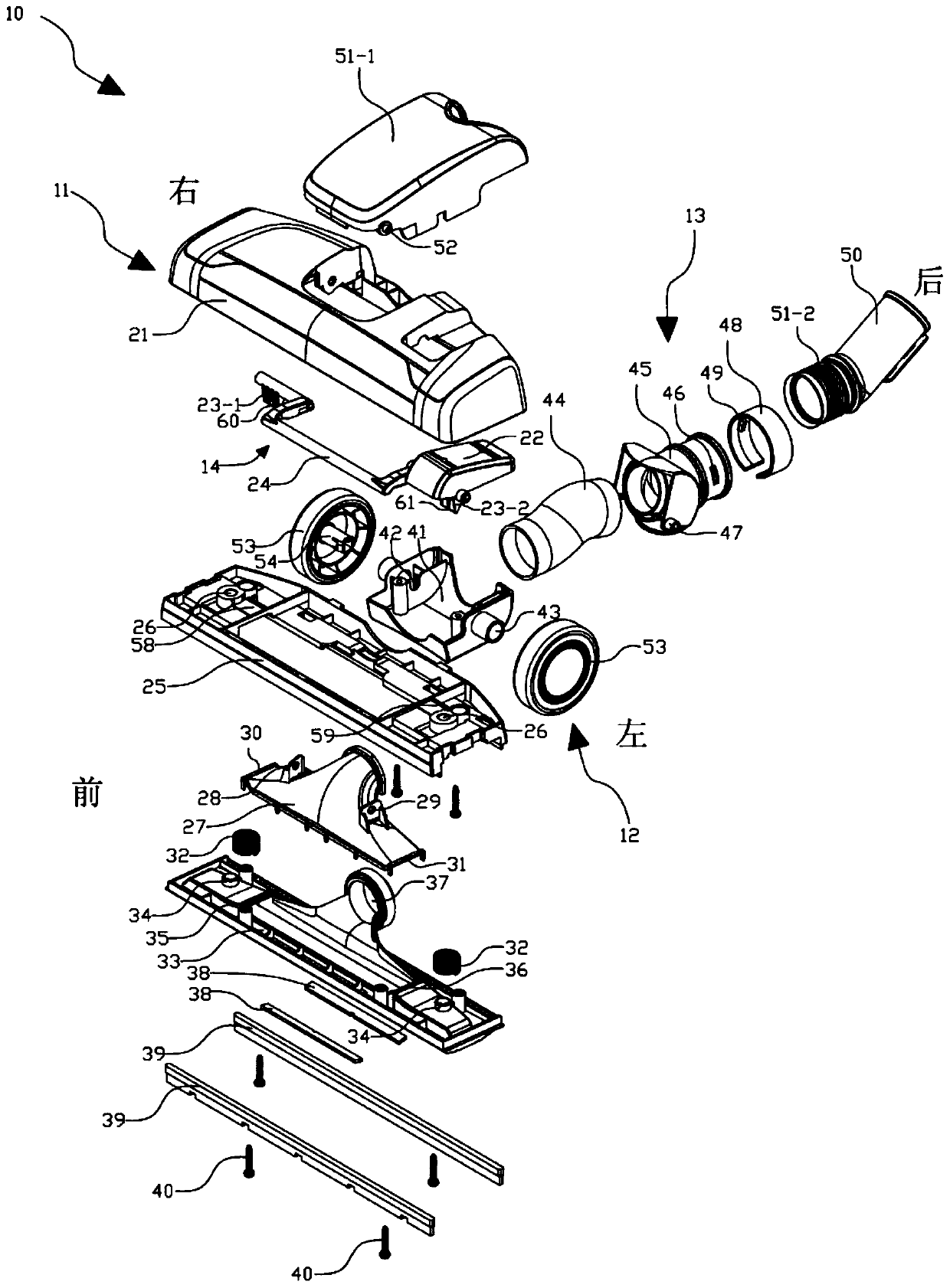
[0025] Hereinafter, the floor brush of the present invention and the vacuum cleaner including the floor brush will be described in detail with reference to the accompanying drawings.

[0026] As a first embodiment, the present invention provides a floor brush, which is used in conjunction with the air duct of a vacuum cleaner to clean the floor, and has such features, including: a main body assembly, including: a bottom plate, provided with a suction slot for sucking air And the air port connected with the air pipe; and the upper cover, which forms a main body cavity with the bottom plate; the air duct assembly, including: the air guide cover, which is connected with the bottom plate to form a suction port for air intake; the hose, whose front end is connected with the air port of the bottom plate , used to guide the wind to enter from the air outlet; elbow sleeve, the front end is connected with the rear end of the hose to prevent air leakage; elbow pipe, the front end is conn...


PUM


Abstract

A floor brush (10) and a vacuum cleaner comprising the floor brush (10). The floor brush (10) is used for cleaning a ground surface in cooperation with an air duct assembly of the vacuum cleaner, and has the following features: a main body component (11); an air duct component (12), comprising a soft tube (44); a soft tube cover plate (51-1) disposed on a top cover (21) and above the soft tube (44), a front end of the soft tube cover plate rotationally connected, by means of a first rotation hinge (52), to an upper portion of an air channel plate (27); a bent tube socket bottom cover (41) located under the location of a connection between the soft tube (44) and a bent tube sleeve (45) and fixedly connected to a rear end of the soft tube cover plate (51-1), the bent tube sleeve (45) being rotationally connected, by means of a second rotation hinge (47), with the bent tube socket bottom cover (41); and a roller wheel component (13). When the floor brush (10) is positioned horizontally and two roller wheels (53) are pressed against the ground surface, the first rotation hinge (52) and the second rotation hinge (47) become parallel to the ground surface. A perpendicular distance between the first rotation hinge (52) to a bottom plate (33) is set as D1, and a perpendicular distance from the second rotation hinge (47) to the bottom plate (33) is set as D2, wherein the first rotation hinge (52) is set higher than the second rotation hinge (47), and D1 = D2 + X, where X is any distance within a range of 4.3 mm to 6.3 mm.

Description

technical field [0001] The invention specifically relates to a floor brush and a vacuum cleaner containing the floor brush. Background technique [0002] Vacuum cleaners have been widely used in ordinary households, and their working principles are basically the same. They all use an electric fan to drive the air to rotate at high speed, thus generating negative pressure and airflow. The airflow contacts the ground through a certain guiding air duct and sucks the dust on the ground. Dust collection device. The floor brush is the part of the vacuum cleaner that is in direct contact with the ground. [0003] The dust collection efficiency of the existing ground brush has reached a bottleneck, in order to improve the efficiency of the vacuum cleaner, the existing conventional means is to increase the dust collection power, and then improve the dust collection efficiency. But adopt this method, still can't overcome a defect-when the vacuum cleaner removes dust, when moving bac...

Claims


Application Information

Patent Timeline
Patent Type & Authority Patents(China)
IPC IPC(8): A47L9/02
CPCA47L9/02
Inventor 彭劲松梁玉
Owner SUZHOU VACS ELECTRICAL
Why Eureka
Try Eureka