
Water diversion annular trough type water outlet bearer

A water-splitting ring, grooved technology, applied in the magnetic circuit shape/style/structure, electric components, cooling/ventilation devices, etc., can solve the problem of affecting the operation safety of the generator, the expansion of the cooling water volume, and the impact on the water outlet support. The problems of arc flat plate and side wall, etc., achieve the effect of novelty, reasonable structure and remarkable technical effect

Active Publication Date: 2017-09-26
HARBIN SHENGDI ELECTRIC POWER EQUIP
View PDF7 Cites 0 Cited by
  • Summary
  • Abstract
  • Description
  • Claims
  • Application Information

AI Technical Summary

Problems solved by technology

[0002] At present, the water-cooled turbogenerator water outlet adopts a flat plate inside the arc on the water outlet support, and the dynamic and static sealing structures of the left and right end covers are relatively simple, and there is still a gap between the inner diameter of the left and right end covers and the outer diameter of the large shaft. With a certain gap, the cooling water flowing out of multiple water outlets will hit the circular arc plate and side wall on the water outlet support at high speed under the centrifugal force of 3000 r / min of the large shaft, causing severe fogging of the cooling water As the volume expands, the water mist will overflow from the gap between the outer diameter of the large shaft and the inner diameter of the left and right end covers, which will seriously affect the operation safety of the generator. outlet support

Method used


Image

  • Water diversion annular trough type water outlet bearer
  • Water diversion annular trough type water outlet bearer

Examples


Embodiment Construction

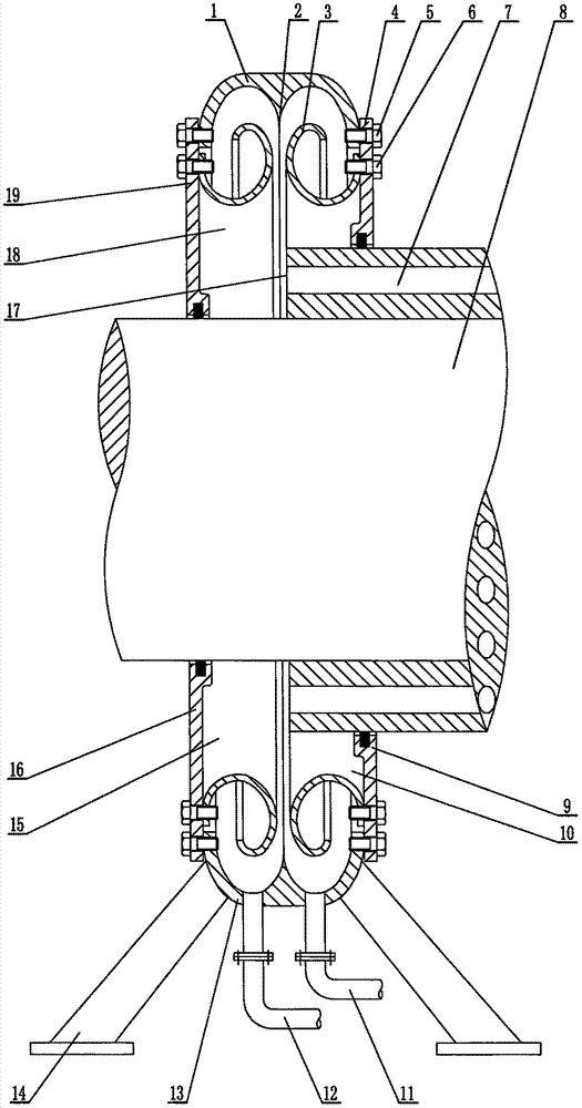
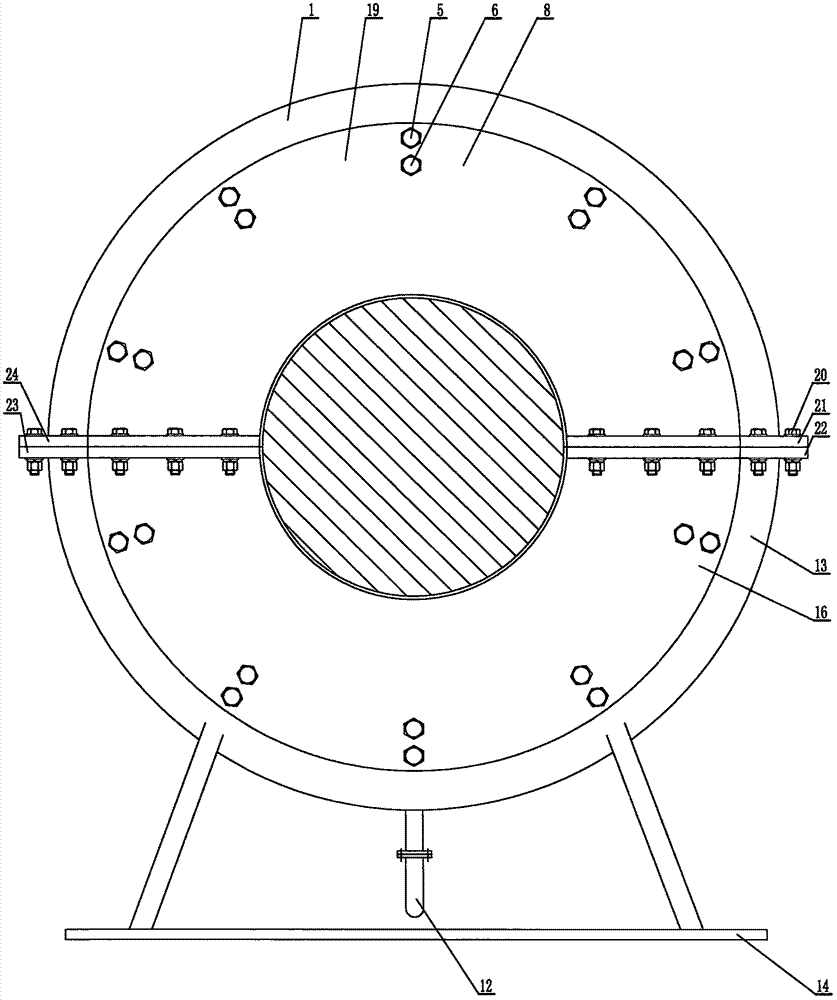
[0017] Fix the upper right water guide ring groove 3 to the upper right end cover 4 with the ring groove bolts 6 respectively, fix the lower right water guide ring groove 10 to the lower right end cover 9, and fix the upper left water guide ring groove 18 to the upper left end cover 19 Up, fix the left lower water guide ring groove 15 on the left lower end cover 16. The right drainage pipe 11 and the left drainage pipe 12 are fixed on the lower water diversion annular guide cavity 13 with two brackets 14 and connected in parallel. Fix the left lower end cover 16 with the left lower water guide ring groove 15 on the left side of the lower water diversion annular guide cavity 13 with the end cover bolt 5, and use the end cover bolt 5 to fix the right lower end cover with the right lower water guide ring groove 10 9 is fixed on the right side of the annular guide cavity 13 in the lower flap. Put the large shaft 8 on the inner diameter of the lower right end cover 9 and the lower ...


PUM


Abstract

The invention discloses a water diversion annular trough type water outlet bearer. Two brackets, a left water discharging pipe and a right water discharging pipe are mounted below a lower water diversion annular guiding chamber. The left water discharging pipe and the right water discharging pipe are communicated with the inner part of the lower water diversion annular guiding chamber. A left lower end cap with a left lower water guiding annular trough and a right lower end cap with a right water guiding annular trough are respectively fixed to the left side and the right side of the lower water diversion angular guiding chamber. A large shaft is arranged above the inner diameters of the left lower end cap and the right lower end cap. A left upper end cap with a left upper water guiding annular trough and a right upper end cap with a right upper water guiding annular trough are respectively fixed to the left side and the right side of an upper water diversion annular guiding chamber. The upper water diversion annular guiding chamber is arranged above the lower water division annular guiding chamber. The upper water diversion annular guiding chamber is fixed to the lower water diversion annular guiding chamber by means of coupling bolts. The upper water diversion annular guiding chamber and the lower water diversion annular guiding chamber are respectively provided with a sharp water diversion semi-ring. The water diversion annular trough type water outlet bearer can be widely applied in the field of a water-cooled steam turbine generator.

Description

Technical field: [0001] The invention mainly relates to a water receiving device on the water outlet of a water-cooled steam turbine generator. Background technique: [0002] At present, the water-cooled turbine generator adopts a flat plate on the water outlet support on the water outlet. The static and dynamic sealing structures of the left and right end covers are relatively simple, and there is a gap between the inner diameter of the left and right end covers and the outer diameter of the main shaft. With a certain amount of clearance, the cooling water flowing out of multiple water outlets will impact on the arc flat plate and side wall of the water outlet support at high speed under the action of the centrifugal force of 3000 rpm of the main shaft, causing severe fogging of the cooling water The water mist will overflow from the gap between the outer diameter of the large shaft and the inner diameter of the left and right end caps, which will seriously affect the operation ...

Claims


Application Information

Patent Timeline
Patent Type & Authority Applications(China)
IPC IPC(8): H02K1/32H02K9/193
CPCH02K1/32H02K9/193
Inventor 吴雳鸣
Owner HARBIN SHENGDI ELECTRIC POWER EQUIP
Learn More