Water source carbon dioxide heat pump system with buffer tank

A technology of carbon dioxide and heat pump systems, applied in heat pumps, refrigeration and liquefaction, lighting and heating equipment, etc., can solve problems such as severe vibration of pipelines

Inactive Publication Date: 2017-09-26
HANGZHOU JIALISI WEIMU NEW ENERGY TECH CO LTD
View PDF0 Cites 1 Cited by
  • Summary
  • Abstract
  • Description
  • Claims
  • Application Information

AI Technical Summary

Problems solved by technology

[0003] The technical problem to be solved and the technical task proposed by the present invention are to overcome the defect that the pipeline is forced to vibrate violently due to the high-pressure air flow inside the existing carbon dioxide unit system plus the periodic pulsation state, and to provide a water source carbon dioxide heat pump system

Method used


Image

  • Water source carbon dioxide heat pump system with buffer tank
  • Water source carbon dioxide heat pump system with buffer tank

Examples


Embodiment Construction

[0034] The present invention will be further described below in conjunction with the accompanying drawings of the description.

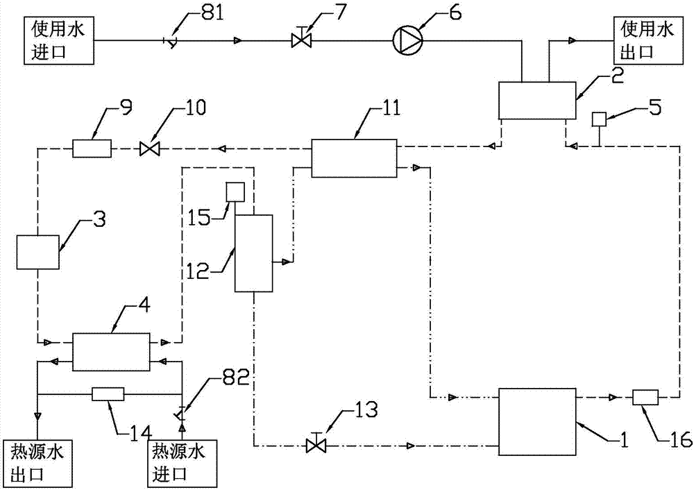
[0035] Such as figure 1 The shown water source carbon dioxide heat pump system with a buffer tank includes a compressor 1, a gas cooler 2, a throttle valve 3, an evaporator 4, a regenerator 11, a gas-liquid separator 12, and an oil return solenoid valve 13;

[0036] Compressor 1 has a carbon dioxide exhaust port, a carbon dioxide gas return port, and an oil return port;

[0037] The gas cooler 2 has a carbon dioxide inlet for heat exchange, a carbon dioxide outlet for heat exchange, a water inlet for heat exchange, and a water outlet for heat exchange;

[0038] The evaporator 4 has a carbon dioxide inlet for heat exchange, a carbon dioxide outlet for heat exchange, a water inlet for heat exchange, and a water outlet for heat exchange;

[0039] The regenerator 11 has a high temperature carbon dioxide inlet, a high temperature carbon dioxide outlet, ...


PUM


Abstract

The invention discloses a water source carbon dioxide heat pump system with a buffer tank, which belongs to the carbon dioxide heat pump system. The internal pressure of the existing carbon dioxide unit system is high, and the water source carbon dioxide unit adopting a piston compressor has periodicity due to the exhaust of the compressor The internal high-pressure airflow plus the periodic pulsation state will cause the pipeline to violently vibrate, which will have an irreversible impact on the safety and long-term stable operation of the system. The buffer tank is connected in series with the carbon dioxide inlet for heat exchange between the gas port and the gas cooler, and the gas flow direction inside the buffer tank is changed to buffer the gas ejected from the cylinder, thereby increasing the resistance coefficient of the air flow pulsation, achieving shock absorption and The purpose of enhancing unit reliability.

Description

technical field [0001] The invention belongs to a carbon dioxide heat pump system, in particular to a water source carbon dioxide heat pump system with a buffer tank. Background technique [0002] The internal pressure of the existing carbon dioxide unit system is high. The water source carbon dioxide unit using the piston compressor has periodic airflow changes due to the exhaust of the compressor. The violent vibration will have an irreversible impact on the safety and long-term stable operation of the system. Contents of the invention [0003] The technical problem to be solved and the technical task proposed by the present invention are to overcome the defect that the pipeline is forced to vibrate violently due to the high-pressure air flow inside the existing carbon dioxide unit system plus the periodic pulsation state, and to provide a water source carbon dioxide heat pump system. [0004] In order to achieve the above object, the water source carbon dioxide heat p...

Claims


Application Information

Patent Timeline
Patent Type & Authority Applications(China)
IPC IPC(8): F25B9/00F25B30/02
CPCF25B9/008F25B30/02F25B2500/13
Inventor 朱利锋饶琨
Owner HANGZHOU JIALISI WEIMU NEW ENERGY TECH CO LTD
Why Eureka
Try Eureka