
Vibrating motor

A vibration motor and vibration direction technology, applied in electrical components, electromechanical devices, etc., can solve the problems of poor connection strength, motor failure, easy deformation, etc., and achieve the effect of low repair rate, prevention of tearing, and stable electrical connection.

Active Publication Date: 2017-09-22
JINLONG MACHINERY & ELECTRONICS CO LTD
View PDF6 Cites 3 Cited by
  • Summary
  • Abstract
  • Description
  • Claims
  • Application Information

AI Technical Summary

Problems solved by technology

[0004] Therefore, the technical problem to be solved by the present invention is to overcome the defects in the prior art that the conductive spring used for flexible electrical connection in the vibration motor and the connection point of the contact is poor in connection strength, easy to deform or even break, and cause motor failure, thereby providing a A vibration motor with more stable electrical connection and lower failure rate

Method used


Image

  • Vibrating motor
  • Vibrating motor
  • Vibrating motor

Examples


Embodiment 1

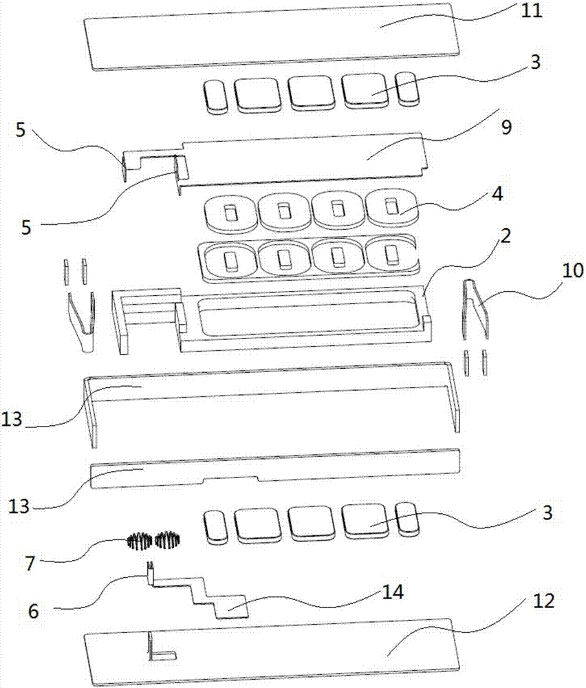
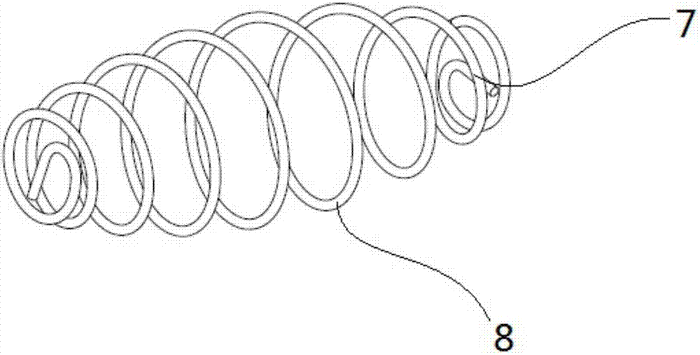
[0051] figure 1 It is an exploded view of the vibration motor provided in Embodiment 1 of the present invention; figure 2 for figure 1 Cutaway view of the vibrating motor shown; image 3 for figure 1 Schematic diagram of the structure of the drum spring shown; Figure 4 for figure 1 Schematic diagram of the structure of the conductive spring shown. Such as Figure 1-4 As shown, the vibration motor provided by this embodiment includes a housing 1 with a housing space, a mass block 2 suspended in the housing space through an elastic member 10, a stator is fixed on the housing, and the stators include housings 1 that are fixedly arranged respectively. The two sets of magnets 3 on the two inner surfaces facing each other, the mass block 2 is located between the two sets of magnets 3, the vibrator includes a coil 4 fixedly arranged on the mass block 2, and the coil 4 is covered with a first coil electrically connected to the coil 4 An FPC board 9 is provided with two moving...


PUM


Abstract

The invention relates to the technical field of a vibrating motor, and particularly relates to a vibrating motor. The vibrating motor comprises a shell, a mass block, a stator, a vibrator and a conductive spring, wherein the shell has an accommodating space; the mass block is suspended in the accommodating space by an elastic part; the stator is arranged in the accommodating space and is fixed on the shell; the vibrator is fixedly arranged on the mass block and can drive the mass block to vibrate in a reciprocating mode relative to the stator; one end of the conductive spring is fixed with the mass block and is electrically connected with a coil; the other end of the conductive spring is fixed with the shell and is electrically connected with a power supply; and in the reciprocating process of the mass block, the conductive spring is always in a non-stretching state. According to the vibrating motor provided by the invention, the conductive spring always in the non-stretching state cannot form a tensile force at a wiring point, so that the wiring point is difficult to fatigue, and a case that the wiring point is broken off in the vibrating process of the mass block can be effectively prevented; and the vibrating motor is more stable in electrical connection, has few faults and is low in repair rate.

Description

technical field [0001] The invention relates to the technical field of vibration motors, in particular to a vibration motor. Background technique [0002] Portable consumer electronic products such as mobile phones, tablet computers, and handheld game consoles are becoming more and more popular among consumers. The above-mentioned electronic products generally use vibration signals for information feedback, such as incoming call reminders for mobile phones, vibration feedback for handheld game consoles, etc. The vibration reminder function has become the most important application of vibration motors in the field of consumer electronics. [0003] Existing linear vibration motors generally use electrified coils as stators, and mass blocks suspended in the motor housing with magnets installed as vibrators. The casing affects the vibration direction of the magnet, causing the magnet to deflect towards the casing, or even sucked to the casing. The casing of this linear vibratio...

Claims


Application Information

Patent Timeline
Patent Type & Authority Applications(China)
IPC IPC(8): H02K33/02
CPCH02K33/02
Inventor 金绍平金士特李中平林丰君
Owner JINLONG MACHINERY & ELECTRONICS CO LTD
Learn More