


Quick Research
Generate reliable direction feasibility study reports for your R&D in just a few steps.

Technical Q&A
Discover and master advanced knowledge NOW. Basics, ideas, possibilities, all at once.

Find Solutions
As an expert in R&D theories, this can generate solutions to your technical problems instantly.

Evaluate Feasibility
Analyze your overall solution with one click, know your potential R&D risks in advance.

Monitor Landscape
Get weekly tech updates, stay abreast of the latest tech innovations and key insights.
A kind of bottom flow energy dissipation device and design method of toe sill and drop sill stilling pool
A bottom flow energy dissipation and design method technology, which is applied in design optimization/simulation, calculation, sea area engineering, etc., can solve problems such as cavitation damage, low pressure at the singularity point in the vortex center, and high strength, so as to avoid cavitation damage and reduce The effect of bottoming flow velocity and enhancing turbulent diffusion
- Summary
- Abstract
- Description
- Claims
- Application Information
AI Technical Summary
Problems solved by technology
Method used
Image

Examples
Embodiment 1
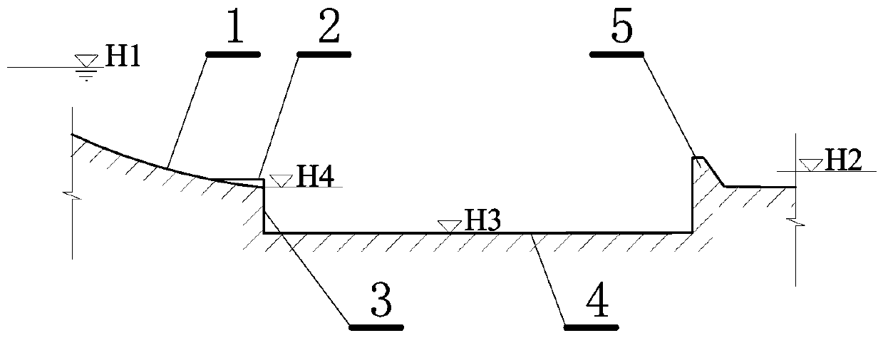
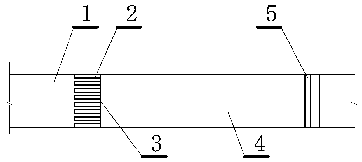
[0042] This embodiment is a kind of bottom flow energy dissipator of toe ridge and fall ridge stilling pool type, such as figure 1 , 2 shown. This embodiment includes: a toe sill 2 arranged at the bottom of the incoming flow slope 1, a falling sill 3 is connected below the toe sill, a stilling pool 4 is set downstream of the toe sill and the falling sill, and the sill Tail sill 5 is set downstream of the force pool.
[0043] The main idea of this embodiment is:
[0044] 1) Several scattered toe sills are set on the first sill of the stilling pool, so that when the water flows through the toe sills, it will form contraction and diffusion water flow on the plane, and the water flow will be high on the vertical surface, increasing the shear area of the water flow into the stilling pool. It strengthens the water flow turbulence and improves the energy dissipation efficiency; at the same time, the setting of the toe sill makes the position of the jump head of the energy dis...
Embodiment 2
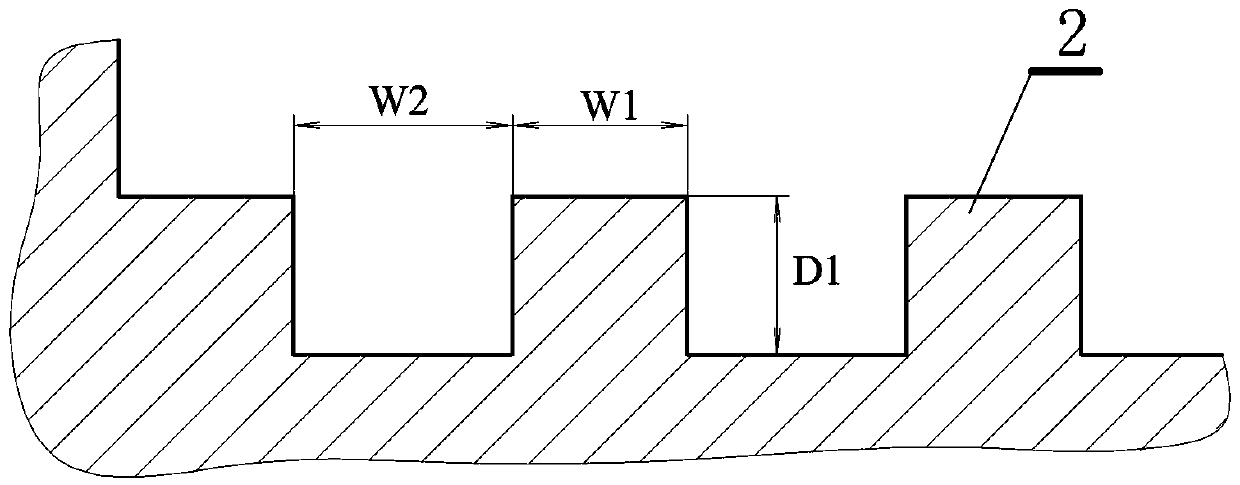
[0050] This embodiment is an improvement of the first embodiment, and is a refinement of the first embodiment on the tooth shape of the toe ridge. The tooth shape of the toe ridge described in this embodiment is: the section perpendicular to the water flow direction is rectangular or square, such as image 3 As shown, the elevation parallel to the direction of water flow is a right triangle whose hypotenuse is a circular arc, such as Figure 4 As shown, the curvature of the arc line is the same as the curvature of the incoming flow slope.
[0051] The toe sill described in this embodiment has a simple shape, is easy to construct, and can be used to reduce construction costs. This kind of toe sill can also be used in the engineering transformation of the existing construction, because there is no earthwork in the construction process, and the toe sill can be directly added to the original drop sill, and the construction cost is very low. This kind of toe sill also has the adv...
Embodiment 3
[0053] A design method for the toe sill and drop sill stilling pool type underflow energy dissipator described in the above embodiments.
[0054] The gist of the present invention is to determine the key dimensions of the toe sill, which are respectively the height of the toe sill D 1. Width of toe sill W 1. Distance between toes W 2, and the drop height D 2.
[0055] Assuming known upstream water level H 1. Downstream water level H 2. Elevation of stilling basin floor H 3. The elevation of the top of the sill is H 4. Single width flow of flood discharge q , stilling basin width w .
[0056] 1. First determine the drop height D 2
[0057] According to the empirical formula, the drop height D 2 can be calculated by the following formula:
[0058] D 2=-0.86Fr+14.18
[0059] Where: Fr is the Freund's number of the water flowing into the stilling tank, which is calculated by the following formula:
[0060] .
[0061] ,
[0062] ,
[0063] in this formula ...
PUM
 Abstract
Description
Claims
Application Information
 - R&D Engineer
- R&D Manager
- IP Professional
- Industry Leading Data Capabilities
- Powerful AI technology
- Patent DNA Extraction
Browse by: Latest US Patents, China's latest patents, Technical Efficacy Thesaurus, Application Domain, Technology Topic, Popular Technical Reports.
© 2024 PatSnap. All rights reserved.Legal|Privacy policy|Modern Slavery Act Transparency Statement|Sitemap|About US| Contact US: help@patsnap.com