Pneumatic bending machine

A bending machine and drive shaft technology, applied in the field of bending devices, can solve the problems of cumbersome operation, low bending accuracy of insulation racks, and low output, and achieve the effect of simple operation principle, simple structure, and low cost

Pending Publication Date: 2017-09-22
宿迁威生金属制品厂
View PDF7 Cites 0 Cited by
  • Summary
  • Abstract
  • Description
  • Claims
  • Application Information

AI Technical Summary

Problems solved by technology

The bending precision of the existing insulation frame is not high, and the bending production cannot be carried out quickly and accurately; the output is low; the operation is cumbersome

Method used


Image

  • Pneumatic bending machine
  • Pneumatic bending machine
  • Pneumatic bending machine

Examples


Embodiment Construction

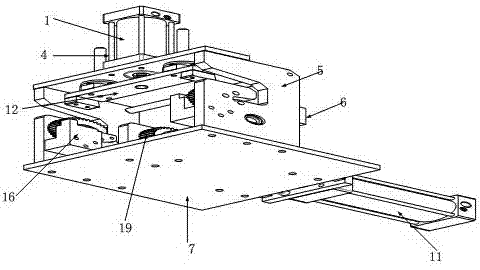
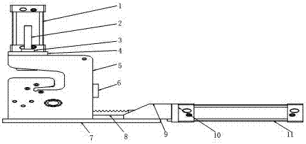
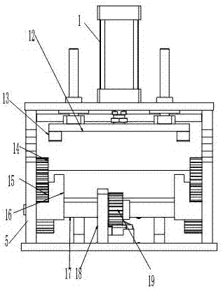
[0012] The preferred embodiments of the present invention are given below in conjunction with the accompanying drawings to describe the technical solution of the present invention in detail.

[0013] Such as Figures 1 to 4 As shown, the pneumatic bending machine of the present invention includes a compression cylinder 1, a guide shaft 2, a guide bearing 3, a compression cylinder flange 4, a side bracket 5, a side bracket reinforcement plate 6, a bottom plate 7, a rack 8, a flange oblique Support 9, driving cylinder flange 10, driving cylinder 11, pressing plate 12, pressing down cutter head 13, driven gear 14, transmission gear 15, lower pad 16, transmission shaft 17, transmission shaft support 18, driving Gear 19, driven gear shaft 20, bending cutter head 21, compression cylinder 1, guide shaft 2, guide bearing 3, compression cylinder flange 4, side support 5 are all located on the top of base plate 7, compression cylinder method The flange 4 is fixed on the top of the side...


PUM


Abstract

The invention discloses a pneumatic bending machine. The pneumatic bending machine comprises a compression air cylinder and other elements, wherein the compression air cylinder, the guide shaft, the guide bearing, the compression air cylinder flange and the side bracket are all located at the top end of the bottom plate; the compression air cylinder flange is fixed to the top end of the side bracket; the guide shaft is fixed to the guide bearing; the guide bearing is fixed to the compression air cylinder flange; the guide shaft is connected with a compression plate; and the compression plate, the downward pressing cutter heads, the driven gears, the transmission gears, the lower cushion blocks, the transmission shaft, the transmission shaft supporting piece, the driving gear, the driven gear shaft, and the bending cutter head are all located inside the side bracket. According to the pneumatic bending machine, the bending and pressing frequency can be effectively decreased, so that one-time forming is achieved; and the production efficiency is improved, the operation principle is simple, and operation is convenient.

Description

technical field [0001] The invention relates to a bending device, in particular to a pneumatic bending machine. Background technique [0002] The warming rack is a kind of food used to store grilled food to keep the food at a certain temperature. The bending precision of the existing thermal insulation frame is not high, and the bending production cannot be carried out quickly and accurately; the output is low; and the operation is cumbersome. Contents of the invention [0003] The technical problem to be solved by the present invention is to provide a pneumatic bending machine, which can effectively reduce the number of times of bending and pressing, and form at one time; improve production efficiency, and has a simple operating principle and convenient operation. [0004] The present invention solves the above-mentioned technical problems through the following technical solutions: a pneumatic bending machine, which is characterized in that it includes a compression cyli...

Claims


Application Information

Patent Timeline
Patent Type & Authority Applications(China)
IPC IPC(8): B21D11/00B21D11/22
CPCB21D11/00B21D11/22
Inventor 钱春宇陈帅施金森
Owner 宿迁威生金属制品厂
Why Eureka
Try Eureka