
Body-cavity effusion drainage system

A effusion and body cavity technology, applied in the field of body cavity effusion drainage system, can solve the problems of uncertain air pressure, gastrointestinal mucosal injury, large pressure difference, etc., and achieve the effect of avoiding process interruption

Inactive Publication Date: 2017-09-22
朱其华
View PDF10 Cites 3 Cited by
  • Summary
  • Abstract
  • Description
  • Claims
  • Application Information

AI Technical Summary

Problems solved by technology

[0002] Extracting body cavity fluid through negative pressure drainage is a common method for clinical diagnosis and treatment, but there are many problems in negative pressure drainage, especially when extracting gastric juice, because the pressure is not easy to control, it may cause damage to the gastrointestinal mucosa of the human body
[0003] Chinese invention patent "Body Cavity Fluid Drainage System" (publication number: 106512112A; publication date: March 22, 2017) discloses a body cavity fluid drainage system, which includes a drainage tube, a connection with the drainage tube An extension tube connected at one end, a negative pressure drainage device connected with the extension tube, and a puncture device is pierced on the other end of the drainage tube; wherein, the negative pressure drainage device is cylindrical, and there is a The upper end of the spring is provided with the first opening connected by the extension tube; through analysis, it can be seen that the volume of the negative pressure drainage device is compressed by pressing the spring, thereby driving out the air inside the negative pressure drainage device, and the spring is released to restore it to its original state, negative pressure. The pressure drainage device returns to its original state. At this time, a negative pressure is formed inside the negative pressure drainage device. It may cause excessive pressure difference and cause damage to the gastrointestinal mucosa of the human body

Method used


Image

  • Body-cavity effusion drainage system
  • Body-cavity effusion drainage system
  • Body-cavity effusion drainage system

Examples


Embodiment Construction

[0021] The preferred embodiments of the present invention will be described in detail below with reference to the accompanying drawings.

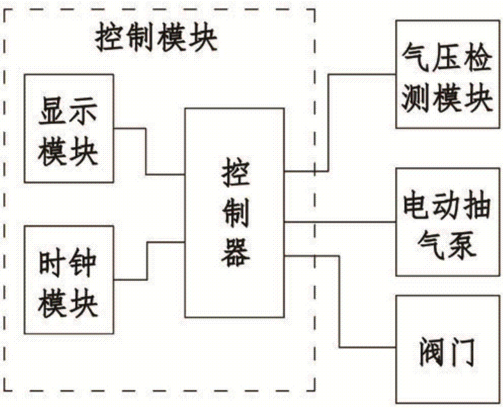
[0022] Such as Figure 1 to Figure 3 As shown; a body cavity effusion drainage system of the present invention includes a control module 1, an electric air pump 2, a sealed liquid storage tank 3, an air pressure detection module 4, an effusion catheter 5, a valve 6 and a liquid extension cylinder 8.

[0023] The electric air pump 2 is provided with an air suction port, and the air suction port communicates with the inside of the sealed liquid storage tank 3 through the air guide tube 7. Here, the electric air pump 2 is located on the left side of the sealed liquid storage tank 3; The interior of the tank 3 is connected, and the liquid accumulation conduit 5 is located on the right side of the sealed liquid storage tank 3; the upper end of the sealed liquid storage tank 3 is provided with two through holes, which are respectively used for in...


PUM


Abstract

The invention discloses a body-cavity effusion drainage system. The body-cavity effusion drainage system includes a control module, an electric air exhaust pump, a sealed liquid storage tank, an air-pressure detecting module, an effusion catheter and a valve, the electric air exhaust pump is provided with an air suction port which is communicated with the interior of the sealed liquid storage tank through an air catheter, the air-pressure detecting module is arranged in the sealed liquid storage tank, one end of the effusion catheter is communicated with the interior of the sealed liquid storage tank, the valve is arranged on the effusion catheter, the control module includes a controller and a display module which is connected with the controller, the controller is in signal connection with the air-pressure detecting module, is connected with the electric air exhaust pump and controls the electric air exhaust pump, and a battery provides power for the controller. According to the body-cavity effusion drainage system, through the air-pressure detecting module, the air pressure in the sealed liquid storage tank is detected, and information is sent to the controller; through the controller, the electric air exhaust pump is controlled to work, so that the air pressure in the sealed liquid storage tank reaches a preset value, in this way, the pressure is controlled, and the situation is avoided that the gastrointestinal mucous membrane of the human body is damaged when body-cavity effusion drainage is conducted.

Description

technical field [0001] The invention belongs to the technical field of medical devices, and in particular relates to a body cavity fluid drainage system. Background technique [0002] Extracting body cavity fluid through negative pressure drainage is a common method for clinical diagnosis and treatment, but there are many problems in negative pressure drainage, especially when extracting gastric juice, because the pressure is not easy to control, it may cause damage to the gastrointestinal mucosa of the human body . [0003] Chinese invention patent "Body Cavity Fluid Drainage System" (publication number: 106512112A; publication date: March 22, 2017) discloses a body cavity fluid drainage system, which includes a drainage tube, a connection with the drainage tube An extension tube connected at one end, a negative pressure drainage device connected with the extension tube, and a puncture device is pierced on the other end of the drainage tube; wherein, the negative pressure ...

Claims


Application Information

Patent Timeline
IPC IPC(8): A61M1/00
CPCA61M1/0023A61M2202/04A61M2205/3334A61M2210/1053A61M1/74A61M1/80A61M2202/0014
Inventor 朱其华
Owner 朱其华
Learn More