Light spot monitoring imaging device

An imaging device and technology of the device, applied in the optical field, can solve the problems of high difficulty in processing and installation, long optical focal length, etc., and achieve the effects of low cost, few optical components, and simple structure

Pending Publication Date: 2017-09-19
11TH RES INST OF CHINA ELECTRONICS TECH GROUP CORP
View PDF6 Cites 0 Cited by
  • Summary
  • Abstract
  • Description
  • Claims
  • Application Information

AI Technical Summary

Problems solved by technology

[0003] The technical problem to be solved by the present invention is to provide a spot monitoring imaging device to solve the problems of long optical focal length and high difficulty in processing and installation of the spot monitoring imaging device in the prior art

Method used


Image

  • Light spot monitoring imaging device
  • Light spot monitoring imaging device

Examples


Embodiment Construction

[0017] The present invention will be described in detail below in conjunction with the accompanying drawings. It should be understood that the specific embodiments described here are only used to explain the present invention, not to limit the present invention.

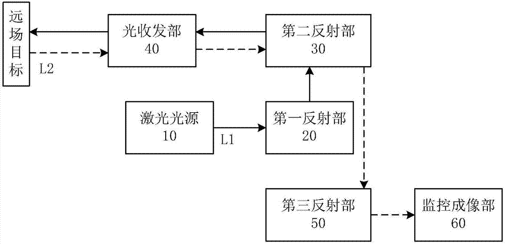
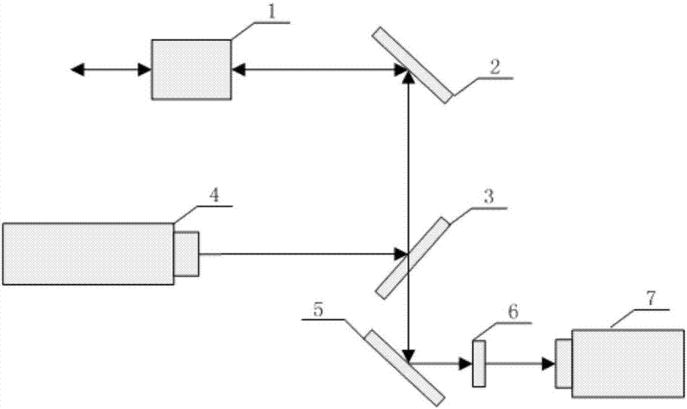
[0018] Such as figure 1 As shown, the embodiment of the present invention provides a spot monitoring imaging device, including:

[0019] The first reflective part 20, the second reflective part 30, the optical transceiver part 40, the third reflective part 50, and the monitor imaging part 60;

[0020] The laser light L1 emitted by the laser light source 10 is reflected by the first reflector 20 and the second reflector 30 in sequence, and then emitted outward by the optical transceiver 40 and focused into a spot image in the far field;

[0021] The light transceiver part 40 detects the diffuse reflection light L2 of the spot image, after the diffuse reflection light L2 is reflected by the second reflection part 30,...


PUM


Abstract

The present invention discloses a light spot monitoring imaging device and belongs to the optical technical field. The invention aims to solve the problems of long optical focal length and high difficulty in processing and installation of a light spot monitoring imaging device in the prior art. The light spot monitoring imaging device includes a first reflecting portion, a second reflecting portion, a light transmitting-receiving portion, a third reflecting portion and a monitoring imaging portion; laser emitted from a laser light source is reflected by the first reflecting portion and the second reflecting portion sequentially, the reflected laser is emitted out through the light transmitting-receiving portion and is focused at a far field so as to form a light spot image; the light transmitting-receiving portion detects the diffusedly reflected light of the light spot image; after the diffusedly reflected light is reflected by the second reflecting portion, part of the diffusedly reflected light skims over the edge of the first reflecting portion and directly enters the third reflecting portion; and the third reflecting portion reflects the part of the diffusedly reflected light which enters the third reflecting portion to the monitoring imaging portion.

Description

technical field [0001] The invention relates to the field of optical technology, in particular to a spot monitoring imaging device. Background technique [0002] With the development of high-power laser technology, the laser strike system has been widely used. In order to achieve the farthest action distance and the best strike effect, it is necessary to ensure the minimum focus of the far-field laser spot. Real-time monitoring of the laser spot on the To distinguish a laser spot with a diameter of several centimeters from several kilometers away, the focal length of the spot monitoring imaging optics is required to be more than 3 meters. Such a long focal length imaging optical system is difficult to design and process, has a large volume and weight, and is expensive, and it is difficult to install it on the tracking and aiming turntable of the laser strike system. Contents of the invention [0003] The technical problem to be solved by the present invention is to provi...

Claims


Application Information

Patent Timeline
Patent Type & Authority Applications(China)
IPC IPC(8): G02B27/48
CPCG02B27/48
Inventor 张海武王岳李松山张文海刘飞刘琳
Owner 11TH RES INST OF CHINA ELECTRONICS TECH GROUP CORP
Why Eureka
Try Eureka