
Guide device for hydrodynamic cleaning of lower surface of first supporting plate of secondary side of steam generator

A steam generator and hydraulic flushing technology, applied in chemical instruments and methods, cleaning methods and utensils, cleaning methods using liquids, etc., can solve the problem of insufficient connection rigidity and inability to adapt to the flushing requirements of the lower surface of the first support plate of the steam generator and other problems to achieve the effect of ensuring rigidity and functional stability, and improving flushing efficiency and accuracy

Pending Publication Date: 2017-09-19
RES INST OF NUCLEAR POWER OPERATION +2
View PDF12 Cites 3 Cited by
  • Summary
  • Abstract
  • Description
  • Claims
  • Application Information

AI Technical Summary

Problems solved by technology

[0004] The purpose of the present invention is to provide a guide device for hydraulic flushing on the lower surface of the first support plate on the secondary side of the steam generator, which solves the problem of insufficient connection rigidity after the barrel structure size of the existing sludge flushing gun is reduced, so that it cannot adapt to the first stage of the steam generator. Washing requirements for the lower surface of the support plate

Method used


Image

  • Guide device for hydrodynamic cleaning of lower surface of first supporting plate of secondary side of steam generator
  • Guide device for hydrodynamic cleaning of lower surface of first supporting plate of secondary side of steam generator

Examples


Embodiment Construction

[0018] The present invention will be further described in detail below in conjunction with the drawings and specific embodiments.

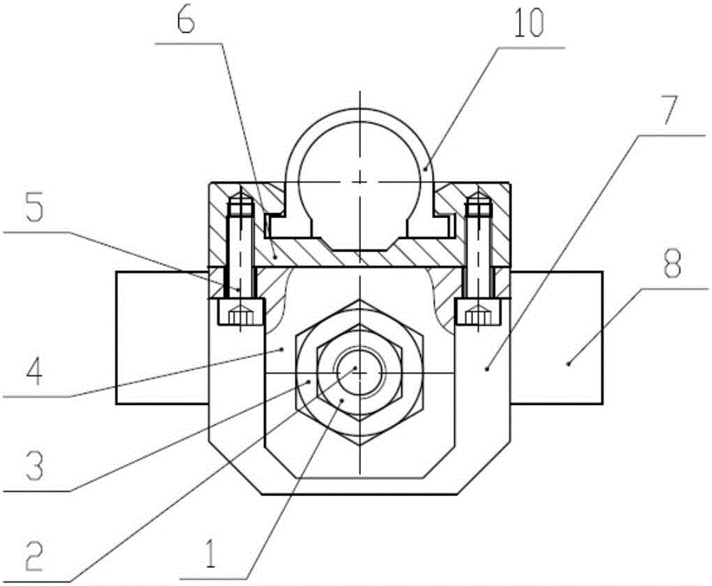
[0019] Such as figure 1 , figure 2 As shown, a hydraulic flushing guide device for the lower surface of the first support plate on the secondary side of the steam generator includes a guide rail 6, a fixed seat 4, a sliding seat 7 and a long screw 2, wherein the guide rail 6 is a grooved rail at the upper end as a whole The right front end forms a hook structure, and a limit screw 11 is set to prevent the slider 10 installed in the upper rail of the guide rail from sliding out of the guide rail 6; the left rear end of the guide rail 6 is fixedly installed with a hexagon socket screw A5 The fixed seat 4 has a threaded hole in the direction parallel to the guide rail 6; the sliding seat 7 located on the right side of the fixed seat 4 is clamped into a section of the sliding groove below the guide rail 6, on the sliding seat 7 and the center of the fix...


PUM


Abstract

The invention relates to the technical field of steam-generator rigid sludge cleaning, and particularly discloses a guide device for hydrodynamic cleaning of the lower surface of a first supporting plate of the secondary side of a steam generator. In the guide device, a guide rail is of a rectangular structure, wherein a groove track is formed in the upper end of the rectangular structure, and the front end of the right side of the guide rail forms a hook structure; a fixed seat is fixed to the lower portion of the rear end of the left side of the guide rail, and a threaded hole is formed in the fixed seat; a slide seat on the right side of the fixed seat is clamped in a section of slide groove of the lower portion of the guide rail; a long threaded rod sequentially penetrates through the slide seat and the fixed seat from the right side of the slide seat, and the end portion of the right side of the long threaded rod is compressed by utilizing a hook fixed on the slide seat; and through rotating the long threaded rod, the slide seat can be driven to move relative to the fixed seat along the guide rail. According to the guide device for hydrodynamic cleaning of the lower surface of the first supporting plate of the secondary side of the steam generator, a guide rail structure is adopted to conduct supporting and guiding on a gun barrel of a sludge cleaning gun, the rigidity and the functional stability of the gun barrel of the cleaning gun are guaranteed, the situation that offset cannot be generated in the stepping process of the sludge cleaning gun is ensured, a nozzle can be aimed at between-tube correctly, and the cleaning efficiency and the accuracy of the lower surface of the first supporting plate are enhanced.

Description

Technical field [0001] The invention belongs to the technical field of rigid sludge washing of a steam generator, and particularly relates to a hydraulic washing guide device for the lower surface of a first support plate on the secondary side of a steam generator. Background technique [0002] Due to the possible serious consequences of sludge deposition on the steam generator, the removal of sludge has become an important part of the maintenance and management of steam generators in nuclear power plants. In order to better solve the problem of sludge deposition, the secondary side of the original evaporator A reverse flushing process is added to the tube sheet flushing process. Backwashing refers to washing the lower surface of the first support plate of the steam generator. [0003] The current sludge flushing gun is mainly for flushing the secondary side tube plate of the steam generator. The available space below the flow distribution plate within the hand hole is large. When...

Claims


Application Information

Patent Timeline
Patent Type & Authority Applications(China)
IPC IPC(8): B08B3/02
CPCB08B3/024
Inventor 杨津瑞张高剑朱立辉张志明李平仁舒芝峰何虹
Owner RES INST OF NUCLEAR POWER OPERATION
Learn More