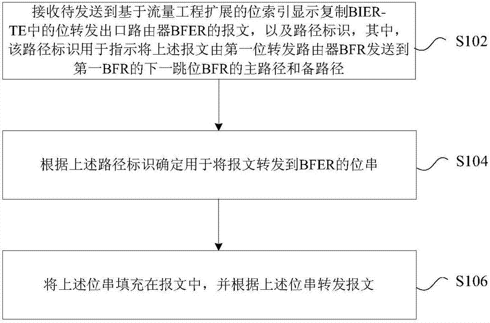
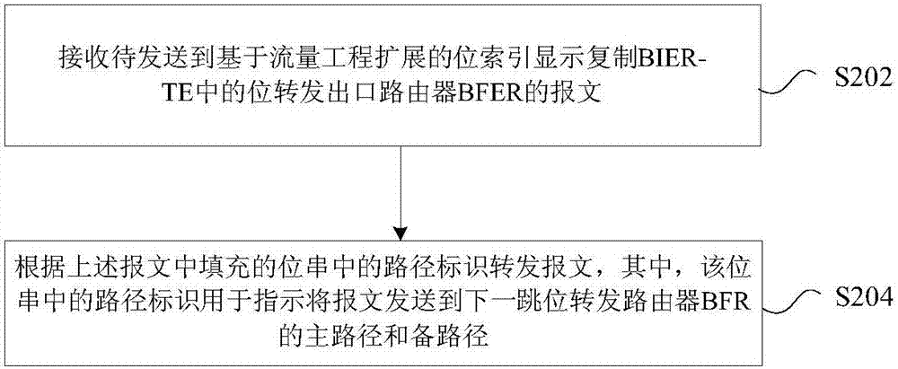
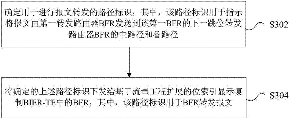
Message forwarding method and device
A message forwarding and message technology, applied in the field of communications, can solve the problems of inability to properly configure path protection and resource waste, and achieve the effect of reasonably and effectively configuring path protection and avoiding resource waste.
- Summary
- Abstract
- Description
- Claims
- Application Information
AI Technical Summary
Problems solved by technology
Method used
Image
Examples
specific Embodiment 1
[0091] Figure 4 It is the forwarding diagram of the BIER FRR message proposed according to Embodiment 1 of the present invention, Figure 5 It is the FRR forwarding table proposed according to Embodiment 1 of the present invention, such as Figure 4 As shown, Pxx represents the bits assigned to the link by the controller, for example, Figure 4 P1 in the table indicates that the controller allocates P1 for the link from BFIR to BFR2, P2 indicates that the controller allocates P2 for the link from BFIR to BFR1, and P12 indicates that the controller allocates FRR from BFIR to BFR2 (the primary path is BFIR-BFR2, and the backup path Assign P12 to BFIR-BFR1-BFR2). Combine below Figure 4 and Figure 5 The process in this embodiment is described, including the following steps:
[0092] Step S401, when the multicast packet arrives at the BFIR node, generate the original BitString as P2, P4, P9, P12, P5, P6, P7, P8, such as Figure 4 shown.
[0093] In step S402, the BFIR for...
specific Embodiment 2
[0096] Figure 6 According to the forwarding diagram of the BIER FRR message proposed in the second embodiment of the present invention, as Figure 6 As shown, Pxx represents the bits allocated by the controller to the link, such as Figure 6P1 in the table indicates that the controller allocates P1 for the link from BFIR to BFR2, P2 indicates that the controller allocates P2 for the link from BFIR to BFR1, and P12 indicates that the controller allocates FRR from BFIR to BFR2 (the primary path is BFIR-BFR2, and the backup path Assign P12 to BFIR-BFR1-BFR2). When the path to BFR2 through BFIR fails, the multicast data packet can reach BFER1 and BFER2 through the backup path BFIR-BFR1. The FRR forwarding table in this embodiment can also refer to Figure 5 , combined below Figure 5 and Figure 6 The process in this embodiment is described, the process includes the following steps:
[0097] Step S501, when the multicast data packet arrives at the BFIR node, generate the or...
specific Embodiment 3
[0108] Figure 9 According to the forwarding diagram of the BIER FRR message proposed in Embodiment 3 of the present invention, Figure 10 It is the FRR forwarding table proposed according to the third embodiment of the present invention, such as Figure 9 As shown, P xx Represents the bits assigned to the link by the controller, such as Figure 9 P1 in the table indicates that the controller allocates P1 for the link from BFIR to BFR1, P4 indicates that the controller allocates P4 for the link from BFR1 to BFR3, and P12 indicates that the controller allocates FRR from BFIR to BFR3 (the primary path is BFIR-BFR3, and the backup path P12 is allocated for BFIR-BFR2-BFR3), and P13 means that the controller allocates P13 for another FRR from BFIR to BFR3 (the primary path is BFIR-BFR3, and the backup path is BFIR-BFR1-BFR3). The process in this embodiment is described below, including the following steps:
[0109] Step S601, when the multicast packet arrives at the BFIR node, ...
PUM
 Abstract
Description
Claims
Application Information
 - R&D Engineer
- R&D Manager
- IP Professional
- Industry Leading Data Capabilities
- Powerful AI technology
- Patent DNA Extraction
Browse by: Latest US Patents, China's latest patents, Technical Efficacy Thesaurus, Application Domain, Technology Topic, Popular Technical Reports.
© 2024 PatSnap. All rights reserved.Legal|Privacy policy|Modern Slavery Act Transparency Statement|Sitemap|About US| Contact US: help@patsnap.com


