Frequency selective surface structure

A technology of frequency selective surface and structural unit, applied in the field of communication, can solve the problems of non-selective frequency of shielding, failure to achieve miniaturization, and large size of frequency selective surface structure.

Active Publication Date: 2017-09-15
XIAN ZHONGXING NEW SOFTWARE
View PDF5 Cites 4 Cited by
  • Summary
  • Abstract
  • Description
  • Claims
  • Application Information

AI Technical Summary

Problems solved by technology

Although shielding boxes and shielding rooms can achieve the function of shielding electromagnetic waves, the frequency of shielding is not selective, and they occupy a large volume and are expensive
The simple dipole frequency selective surface has frequency selective characteristics for specific electromagnetic waves. Due to its simple structure, it shows different transmission characteristics for electromagnetic waves incident at different angles, and its stability is poor, and its frequency selective surface structure size is relatively small. Large, can not achieve the effect of miniaturization
[0005] It can be seen that none of the existing frequency selectors can meet the requirements of miniaturization, and the general frequency selection surface is a half-wavelength resonator. In actual design and application, it is impossible to make the size large enough to meet the resonance at a specific frequency; Therefore, there is an urgent need for a miniaturized frequency-selective surface structure, which can meet the needs of miniaturization while having frequency-selective properties.

Method used


Image

  • Frequency selective surface structure
  • Frequency selective surface structure
  • Frequency selective surface structure

Examples


Embodiment 1

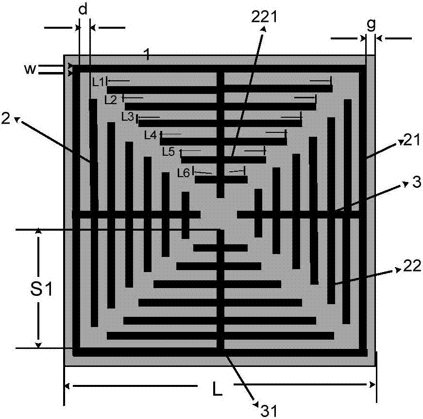
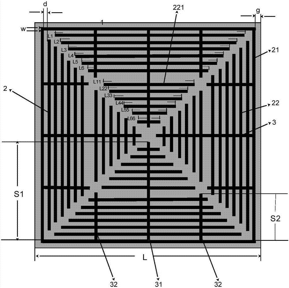
[0044] In the frequency selective surface structure unit, a dielectric substrate with a thickness of 1 mm, a dielectric constant of 4.3, and a tangent loss of 0.025 is used. Formed on the dielectric substrate in the form of metal patches such as figure 2 In the structure shown, the number n of square rings in the slit square ring array is 12, wherein 6 slit square rings intersect with the first metal strip 31 and the second metal strip 32 at the same time, and their lengths are L1, L2, L3 respectively , L4, L5, L6, the 6 square rings do not intersect with the second metal strip 32, but only intersect with the first metal strip 31, and their lengths are respectively L11, L22, L33, L44, L55, L66, specifically:

[0045] A square ring structure and a closed square ring metal wire are arranged on the mechanism plane of the dielectric substrate. The side length of the closed square ring metal wire is L=8.7mm, and there is a square ring array of gaps inside the closed square ring me...

Embodiment 2

[0056] The frequency selective surface structure unit provided by the embodiment of the present invention and the frequency selective surface structure composed thereof are versatile, and the resonant length is increased by further reducing the distance d between the metal lines and the width w of the metal strip, thereby reducing the resonant frequency ; It is also possible to increase the resonant frequency by appropriately increasing the distance d between the metal lines and the width w of the metal strip, so as to achieve the effect of filtering out electromagnetic waves of a certain frequency.

[0057] This example is to increase the spacing d between the metal lines and the width w of the metal strips and change the unit size L to reduce the resonance wavelength to filter out electromagnetic waves with a frequency of 5.1GHz. The thickness is 1mm, the dielectric constant is 4.3, and the tangent loss is 0.025 dielectric substrate, the number of square rings in the slit squ...


PUM

PropertyMeasurementUnit
Widthaaaaaaaaaa
Thicknessaaaaaaaaaa
Side lengthaaaaaaaaaa

Abstract

The invention discloses a frequency selective surface structure. The frequency selective surface structure unit comprises a dielectric substrate (1), a square ring array (2) and metal strips (3), wherein the square ring array (2) is arranged on a dielectric plane of the dielectric substrate (1) and comprises sealed square ring metal lines (21) and gap square ring arrays (22), the sealed square ring metal lines (21) are arranged at four strip edges of the dielectric substrate (1), the gap square ring arrays (22) are arranged in the sealed square ring metal lines (21), share same center with the sealed square ring metal lines (21) and are sequentially arranged, the gap square ring arrays (22) are provided with two diagonal line gaps which are crossed, each gap square ring of the gap square ring arrays (22) is divided into four metal lines (221) in different directions by the diagonal line gaps, the metal strips comprise first metal strips (31), the first metal strips (31) perpendicularly intersect with the sealed square ring metal lines (21) and each metal line (221) of the gap square ring arrays (22) in a corresponding direction.

Description

technical field [0001] The invention relates to the communication field, in particular to a frequency selective surface structure unit and a frequency selective surface structure formed therefrom. Background technique [0002] In the process of implementing the technical solutions of the embodiments of the present application, the inventors of the present application at least found the following technical problems in the related art: [0003] With the rapid development of wireless communication, whether it is radar, electronic countermeasure technology, or personal communication system, its rapid development has played a role in promoting the microwave field. In many fields, a system is required to select the frequency of specific electromagnetic waves, such as: microwave filters, shielded boxes and shielded rooms, simple dipole frequency selective surfaces, etc. [0004] Among them, there are many types of microwave filters, including filters composed of lumped parameters,...

Claims


Application Information

Patent Timeline
IPC IPC(8): H01P1/20
CPCH01P1/2002H01P1/20
Inventor 王龙龙
Owner XIAN ZHONGXING NEW SOFTWARE
Why Eureka
Try Eureka