A vehicle cooling system
A technology for cooling systems and vehicles, applied in engine cooling, coolant flow control, machine/engine and other directions, can solve the problems of large flow energy loss, inability to distribute on demand, inability to achieve large flow, etc., to avoid energy consumption. Loss of consumption, the effect of flexible control
- Summary
- Abstract
- Description
- Claims
- Application Information
AI Technical Summary
Problems solved by technology
Method used
Image
Examples
Embodiment 1
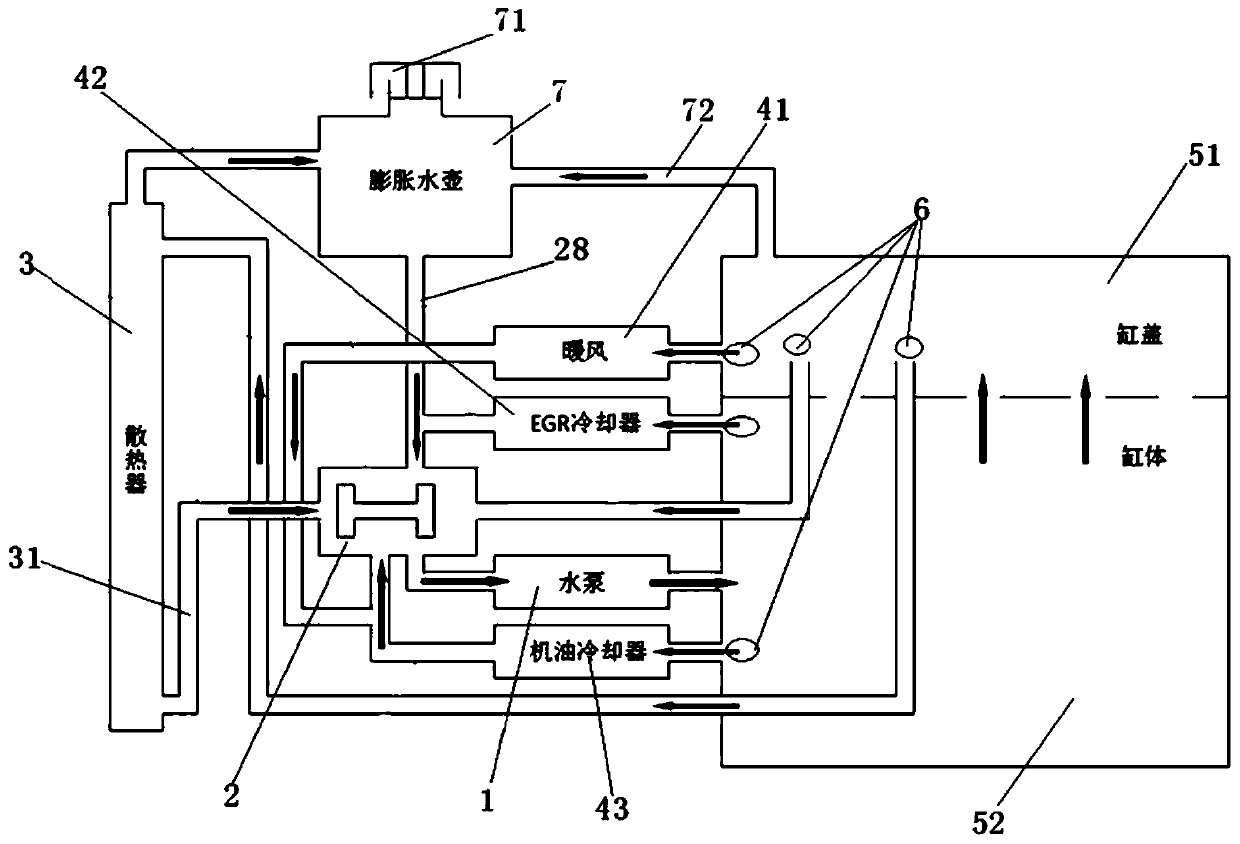
[0032] Such as figure 1 shown, see also figure 2 , the present invention provides a vehicle cooling system according to an embodiment. The vehicle cooling system includes a radiator 3, a cylinder body 52, a cylinder head 51, a flow control structure 2, a warm air return pipeline 41, and an oil cooler return pipeline 43 , the cooler return water pipeline 42 and the water pump 1, the flow control structure 2 includes a water temperature sensor 6, a control structure and a main valve structure,
[0033] The cylinder head 51 is connected to the water inlet of the warm air return pipeline 41, the cylinder head 51 is also connected to the water inlet of the radiator 3 through the water inlet pipeline, and the cylinder body 52 is respectively connected to the oil cooler return water pipeline The water inlet of 43 and the water inlet of the cooler return water pipeline 42 are connected, and the main valve structure is arranged between the water outlet pipeline 31 of the radiator 3 a...
Embodiment 2
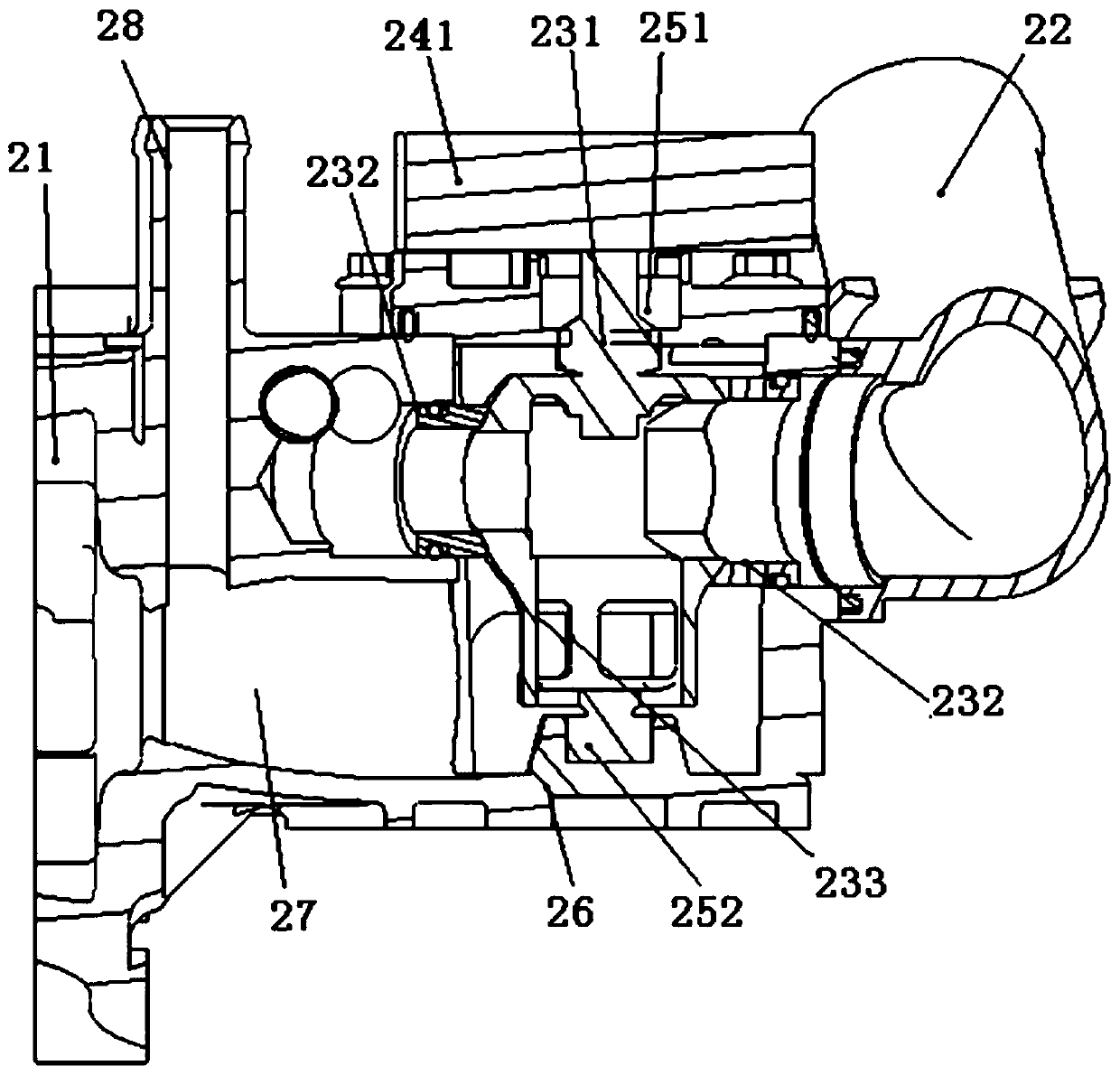
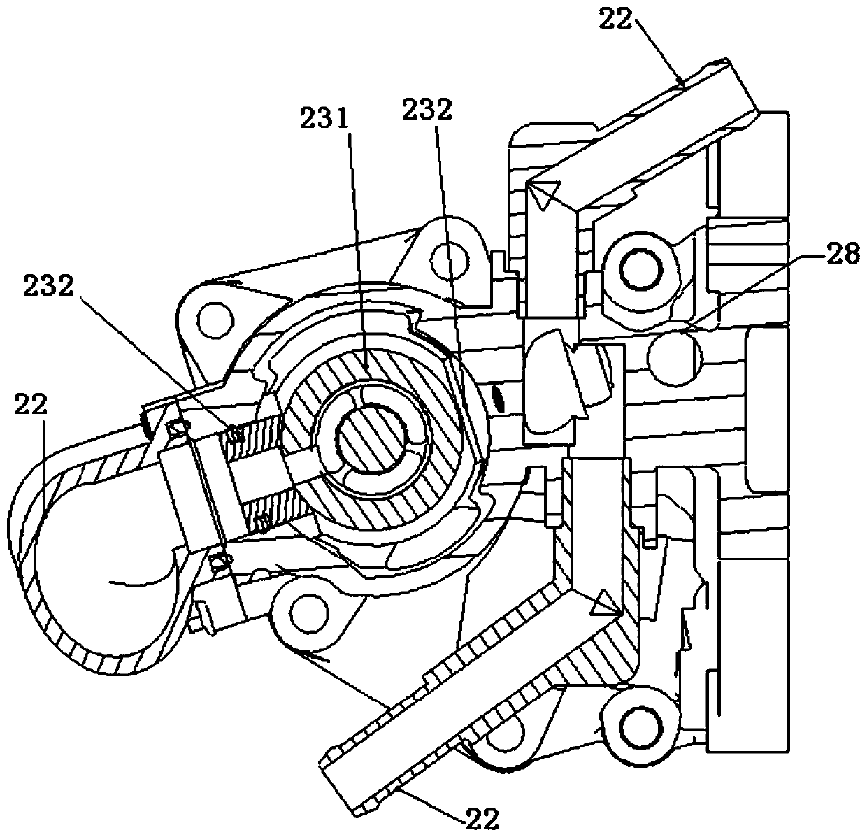
[0044] The embodiment of the present invention describes the specific situation of the flow control structure, such as figure 2 shown, see also image 3 , the embodiment of the present invention provides a flow control structure applied to the vehicle cooling system, the flow control structure includes: a water temperature sensor 6, a control structure and a main valve structure, and each water flow branch 22 is provided with the water temperature sensor 6. The main valve structure is arranged at the water outlet of each water flow branch 22, and the water temperature sensor 6 is sequentially connected with the control structure and the main valve structure;
[0045] When working, the water temperature sensor 6 sends the water temperature signal of the water flow branch 22 to the control structure, and the control structure controls the main valve structure to open or close the water flow branch 22; when the main valve structure opens any water flow When the branch 22 is use...
Embodiment 3
[0061] The embodiment of the present invention describes in detail the specific conditions of the water pump: as Figure 4 shown, see also Figure 5, the present invention provides a clutch type electric control water pump, the clutch type electric control water pump includes a water pump body, a clutch structure, and the clutch structure includes a driving mechanism 12, a clutch shoe 13, a clutch disc 14 and a one-way bearing 16, The driving mechanism 12 is arranged on the casing 11 of the water pump body, and the driving mechanism 12 is connected with the clutch shoe 13, the driving mechanism 12 is used to drive the clutch shoe 13 to move, the The clutch disc 14 is connected with the bearing 15 of the water pump body, the one-way bearing 16 is arranged between the bearing 15 of the water pump body and the pulley 17, and the inner ring 161 of the one-way bearing 16 is connected with the water pump body The bearing 15 is connected, and the outer ring 162 of the one-way bearin...
PUM
 Abstract
Description
Claims
Application Information
 - R&D
- Intellectual Property
- Life Sciences
- Materials
- Tech Scout
- Unparalleled Data Quality
- Higher Quality Content
- 60% Fewer Hallucinations
Browse by: Latest US Patents, China's latest patents, Technical Efficacy Thesaurus, Application Domain, Technology Topic, Popular Technical Reports.
© 2025 PatSnap. All rights reserved.Legal|Privacy policy|Modern Slavery Act Transparency Statement|Sitemap|About US| Contact US: help@patsnap.com


