
Traction spherical hinge for rail vehicles and rigidity design method of traction spherical hinge

A rail vehicle and stiffness design technology, applied in the direction of springs, devices that move laterally between the chassis and the bogie, can solve problems such as short fatigue life, wrinkle cracking, and inability to meet nonlinear stiffness requirements, and achieve improved resistance. Fatigue performance, rubber swelling reduction effect

Active Publication Date: 2017-09-15
ZHUZHOU TIMES NEW MATERIALS TECH
View PDF10 Cites 11 Cited by
  • Summary
  • Abstract
  • Description
  • Claims
  • Application Information

AI Technical Summary

Problems solved by technology

[0005] 1. Different operating conditions have different rigidity requirements for the ball joint during the loading process. In order to better meet the dynamic requirements and safety of the vehicle, the ball joint requires its radial, axial, deflection and torsional stiffness. It meets the load-bearing requirements of the operating conditions, but the structure of the existing spherical joint is difficult to adjust the four rigidities of the spherical joint according to the load-bearing requirements of the operating conditions
[0006] 2. The rubber profile in the ball joint adopts an inwardly recessed U-shaped structure, which is prone to wrinkle cracking and extrusion cracking under heavy loads, and has a short fatigue life.
[0007] 3. The nonlinear stiffness characteristics of the spherical joint in the bearing process are not high, which cannot meet the nonlinear stiffness requirements under large loads
In this solution, the length of the rubber gradually increases from the side that is in contact with the jacket to the side that is in contact with the mandrel. When compressed, the side of the rubber layer will not form wrinkles, but will be close to the jacket to reduce the amount of rubber. layer cracking and wrinkling, but this scheme does not give how to improve the four stiffness and nonlinear stiffness characteristics of the spherical joint according to the load-bearing requirements

Method used


Image

  • Traction spherical hinge for rail vehicles and rigidity design method of traction spherical hinge
  • Traction spherical hinge for rail vehicles and rigidity design method of traction spherical hinge
  • Traction spherical hinge for rail vehicles and rigidity design method of traction spherical hinge

Examples


Embodiment Construction

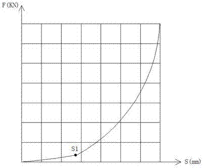
[0028] Attached below Figures 1 to 3 Embodiments of the present invention are described in detail.

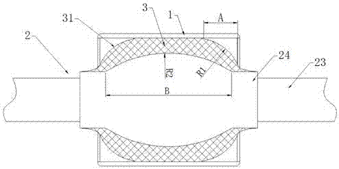
[0029] A traction ball joint for rail vehicles, comprising a casing 1, a mandrel 2, and a rubber layer 3 vulcanized and bonded between the mandrel 2 and the casing 1, and is characterized in that the middle of the bonding part between the mandrel 2 and the rubber layer 3 is The segment is an arc surface protrusion 21 protruding radially outward, the center line of the arc surface protrusion 21 coincides with the center line of the mandrel 1, and the deformed surface 31 of the rubber layer 3 is axially outward The inner surface gradually approaches the outer convex arc surface of the inner wall of the jacket 1, the arc radius of the deformed surface 31 is R1, and the arc radius of the arc surface protrusion 21 is R2, R1<R2.

[0030] As shown in the figure, the mandrel 2 has an arc-shaped protrusion 21, and the deformed surface of the rubber layer 3 is an outwardly convex arc-s...


PUM


Abstract

A traction spherical hinge for rail vehicles comprises a case, a mandrel and a rubber layer bonded between the case and the mandrel through vulcanization. The traction spherical hinge is characterized in that the middle section of a bonding part for the mandrel and the rubber layer is an arc surface bulge bulging outwards in the radial direction, the center line of the arc surface bulge coincides with that of the mandrel, the deformation profile of the rubber layer is a convex arc surface gradually getting close to the inner wall of the case from outside to inside in the axial direction, the arc radius of the deformation profile is R1, the arc radius of the arc surface bulge is R2, and R1 is smaller than R2. Rigidity adjustment can be performed on the axis, diameter, deviation and torque of the spherical hinge can be realized, and the non-linear rigidity characteristics and fatigue resistance of the spherical hinge in the bearing process can be improved. The invention further provides a rigidity design method of the traction spherical hinge for the rail vehicles.

Description

technical field [0001] The invention relates to a traction ball joint for rail vehicles and a stiffness design method thereof, belonging to the technical field of rail vehicle elastic components. Background technique [0002] The ball joint is a commonly used rubber-metal composite vibration damping and connecting element. Its main function is to connect the car body and the frame. [0003] The original that can transmit force and provide multi-directional cushioning. The metal parts and rubber are vulcanized into a whole under certain temperature and pressure through the adhesive. [0004] With the increase of rail vehicle lines, the operating conditions of each line are not the same. The defects of the existing spherical joints are: [0005] 1. Different operating conditions have different requirements for the stiffness of the ball joint during the loading process. In order to better meet the dynamic requirements and safety of the vehicle, the ball joint requires its r...

Claims


Application Information

Patent Timeline
Patent Type & Authority Applications(China)
IPC IPC(8): B61F5/24F16F1/393
CPCF16F1/393B61F5/24
Inventor 黄江彪冯万盛陈俊辉肖祥龙张玉祥罗俊
Owner ZHUZHOU TIMES NEW MATERIALS TECH
Learn More