
Round bar machining device and feeding device thereof

A processing equipment and processing device technology, applied in metal processing equipment, metal processing, grinding/polishing equipment, etc., can solve problems such as increased labor costs, processing abnormalities, sticking and non-rolling blocking of feed ports, etc., to reduce Labor cost, the effect of improving production efficiency

Pending Publication Date: 2017-09-15
深圳市引领工业装备有限公司
View PDF7 Cites 3 Cited by
  • Summary
  • Abstract
  • Description
  • Claims
  • Application Information

AI Technical Summary

Problems solved by technology

[0002] The general raw material of the cutting tool used in the drilling and milling process is a slender round bar, which needs to be cut into the required length according to the required length. Most of the existing cutting processing equipment uses semi-automatic or rolls the bar in the inclined groove to load the material. In the case of semi-automatic, a special station needs to be equipped with a manual during the processing to continuously replenish the round bar; while the previous fully automatic feeding relies on the rolling of the bar to load the material, which often causes sticking between the bars due to water or dust. There is an abnormality in the rolling blockage of the feed inlet, so it is also necessary to be equipped with manual monitoring of the processing status, which increases labor costs and processing abnormalities

Method used


Image

  • Round bar machining device and feeding device thereof
  • Round bar machining device and feeding device thereof
  • Round bar machining device and feeding device thereof

Examples


Embodiment Construction

[0023] Typical embodiments that embody the features and advantages of the present invention will be described in detail in the following description. It should be understood that the present invention is capable of various changes in different embodiments without departing from the scope of the present invention, and that the description and illustrations therein are illustrative in nature and not limiting. this invention.

[0024] The present invention will be described in further detail below in conjunction with the accompanying drawings and embodiments.

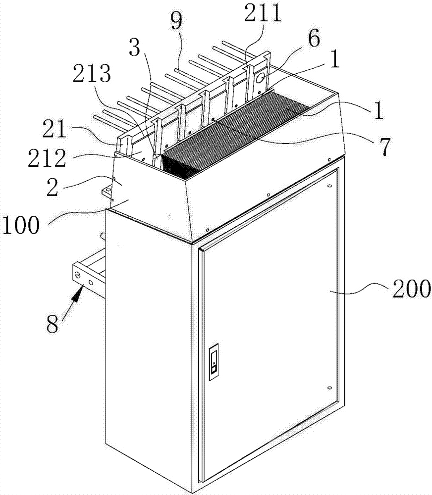
[0025] The round bar processing equipment of the present embodiment comprises: a feeding device and a processing device, and the processing device can be a cutting device or a grinding device; the round bar is sent to the processing device by the feeding device, and the round bar is processed The unit is finished cutting or sanding.

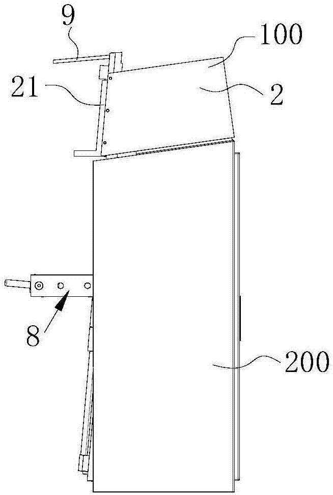
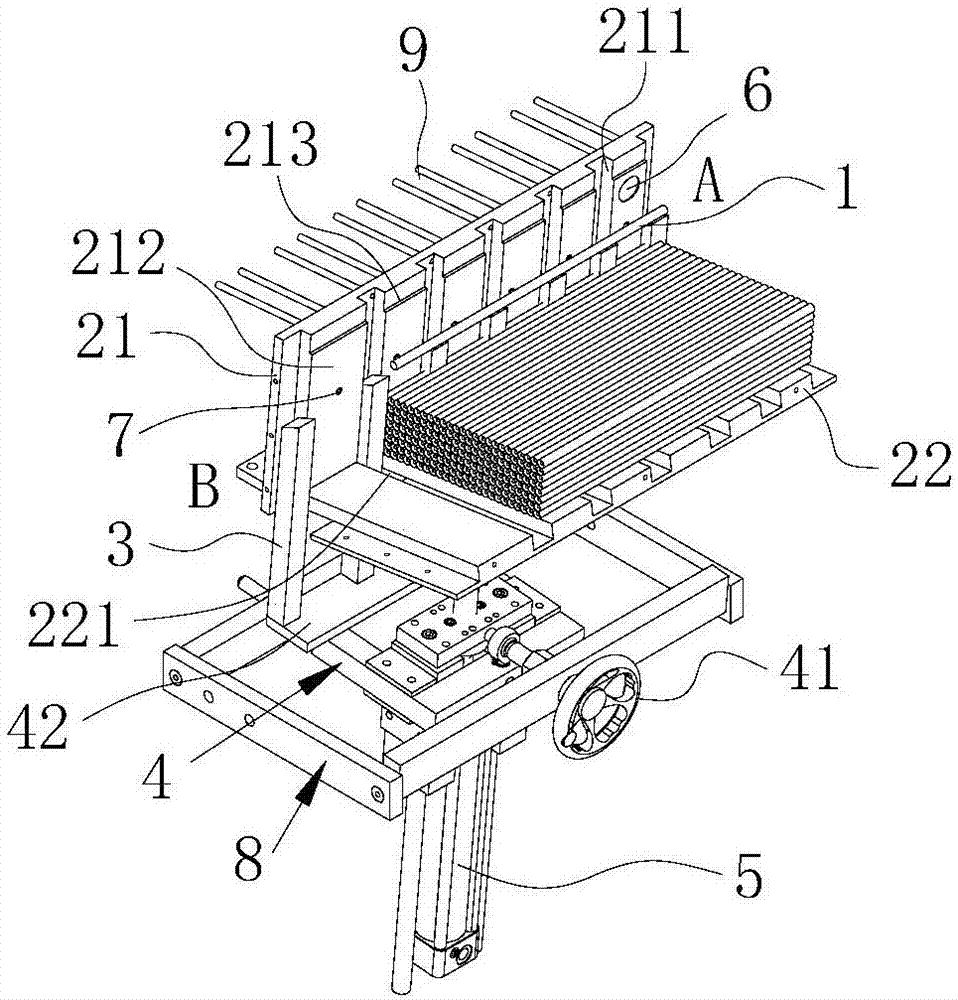
[0026] refer to Figure 1 to Figure 7 , The feeding device of the round bar material p...


PUM


Abstract

The invention provides a round bar machining device and a feeding device thereof. The feeding device comprises a loading box, multiple pushing rods, an adjusting mechanism and a power mechanism; the loading box is of a box structure with an opening in the upper and is used for bearing round bars, multiple vertically through grooves are formed in the inner surface of one side wall of the loading box, multiple pushing stop faces are formed by the non-groove position of the inner surface of the side wall of the loading box, the multiple pushing rods stretch into the loading box from the lower portion of the loading box, and the pushing rods are opposite and close to the grooves; the adjusting mechanism is connected with the pushing rods and can drive the pushing rods to move in the direction facing or away from the grooves, the pushing rods are partly embedded in or moved out of the grooves, the top faces of the pushing rods partly or completely exceed the pushing stop faces, and the exceeding faces form pushing faces suitable for a single round bar; and the power mechanism is connected with the pushing rods so as to drive the pushing rods to vertically move.

Description

technical field [0001] The invention relates to the field of cutting processing equipment, in particular to a round bar material processing equipment and a feeding device thereof. Background technique [0002] The general raw material of the cutting tool used in the drilling and milling process is a slender round bar, which needs to be cut into the required length according to the required length. Most of the existing cutting processing equipment uses semi-automatic or rolls the bar in the inclined groove to load the material. In the case of semi-automatic, it is necessary to equip a special station and a manual during the processing to continuously replenish the round bar; while the previous fully automatic feeding relies on the rolling of the bar to load the material, which often causes sticking between the bars due to water or dust. There is an abnormality in the rolling blockage of the feed inlet, so it is also necessary to be equipped with manual monitoring of the proce...

Claims


Application Information

Patent Timeline
Patent Type & Authority Applications(China)
IPC IPC(8): B23Q7/00B24B41/00
CPCB23Q7/006B24B41/005
Inventor 贺忠华王华
Owner 深圳市引领工业装备有限公司
Learn More