
Circular pin combination device and circular pin ejection method

A technology combining device and ring pin, applied in the directions of packaging, transportation and packaging, labeling, etc., can solve the problems of double inner winding type winding that is difficult to easily remove, vibrate or shake, etc., to improve work efficiency, remove mutual entanglement, prevent The effect of the jam

Active Publication Date: 2010-06-16
克铁库存斯股份有限公司
View PDF2 Cites 3 Cited by
  • Summary
  • Abstract
  • Description
  • Claims
  • Application Information

AI Technical Summary

Problems solved by technology

[0033] Among them, by such as Figure 2A The entanglement between the filaments caused by the type of inner entanglement shown can be relatively easily released by vibration and other pressing forces, but if Figure 2B The outer winding type shown and the Figure 2C The type of double inner wrap shown is not easily unwound
[0034] In addition, it has been determined that the inner winding type occurs mainly because the upper part of the ring pin piece, in which the filament portion mounted on the ring pin coupling device is formed in a curved shape, vibrates in most cases. or shaking; or in the state where the lower part of the ring pin is fixed, its upper part is roughly bent 90° toward the direction where the filament part of the curved ring is formed. It is also easy to occur when the ring pin is taken out of the housing
[0035] In addition, it has been judged that the above-mentioned outer winding type is mainly caused by the following reason in most cases: in the state where the upper part of the ring pin is fixed, the lower part of the ring pin is directed toward the filament part where the curved ring is formed. The direction of the ring pin is roughly bent by 90°. In this case, the ring pin piece is mounted on the ring pin joint device during the loading operation or the ring pin piece mounted on the ring pin joint device responds to the driving operation. , and it is easy to occur when moving slowly downward
[0036] In addition, when the outer winding type is determined, the ring pin piece is also stored in the packaging case or taken out from the case, and when the ring pin piece is mounted on the ring pin coupling device. It is easy to occur during carrying operation

Method used


Image

  • Circular pin combination device and circular pin ejection method
  • Circular pin combination device and circular pin ejection method
  • Circular pin combination device and circular pin ejection method

Examples


Embodiment Construction

[0064] The configuration of a specific example of the ring and pin coupling device according to the present invention will be described in detail with reference to the drawings.

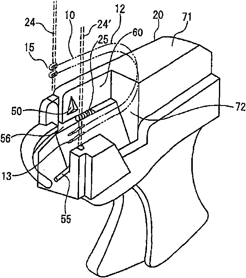
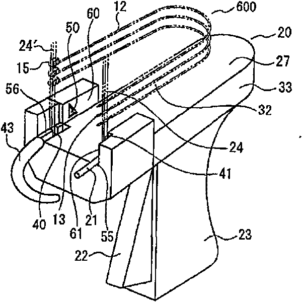
[0065]That is, FIG. 1 is a diagram showing the structure of a specific example of the first aspect of the present invention. In the figure, the ring pin 10 has: a flexible filament portion 12; An insertion portion 13 with a suitable fastening portion 13 at the end; an insertion portion 15 provided at the other end of the filament portion 12 with a hole for preventing reverse passage through the insertion portion 13 The ring pin coupling device 20 is configured such that a ring pin piece 600 formed by arranging a plurality of ring pins 10 in parallel with each other with appropriate connecting band portions 24 is inserted and mounted in a state in which the filament portion 12 is bent into a curved shape. The specified part of the body part, so that each ring pin is sequentially driven out, and the ri...


PUM


Abstract

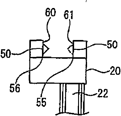
The present invention relates to a circular pin combination device which is provided with a winding releasing mechanism that actively release the winding part when winding of circular pin sheets occurs on the circular pin combination device. On the circular pin combination device (20), a random part selected from a part near an ejection part (56) of a socket (15) and a part near an ejection part (55) of an insertion-through part (13) is provided with the winding releasing mechanism (50) which exerts a pressing force in a direction crossed with an axial direction of a filament part (12) to one part of the filament part (12) that is next to the socket (15) or the insertion-through part (13).

Description

technical field [0001] The present invention relates to a loop pin capable of binding clothes, socks, etc. into a bundle, or inserting one end of a loop pin into a product, thereby attaching labels such as trademark labels, price labels, raw material instructions, instruction manuals, etc. Combined device and ring pin driving method. Background technique [0002] In the past, various ring pins and ring pin coupling devices were generally used in order to efficiently bundle clothes such as ties and shirts, daily small items, umbrellas, slippers, socks, etc., or to effectively attach trademark labels and price tags to corresponding products. . [0003] For the structure of a specific example of the ring pin 10 in the prior art, refer to Figure 9 to Figure 13 Be explained. [0004] which is, Figure 9 The ring pin 10 involved has: a flexible filament portion 12; an insertion portion 13 having a suitable engaging portion 16 provided at one end of the filament portion 12; a s...

Claims


Application Information

Patent Timeline
IPC IPC(8): B65C7/00
Inventor 上野良明
Owner 克铁库存斯股份有限公司
Learn More