Method, device and computer storage medium for determining Poynting vector of seismic wavefield

A technology of Poynting vector and seismic wave field, which is applied in the field of seismic exploration and can solve problems such as influence and influence on the generation of ADCIGs gathers

Active Publication Date: 2019-05-07
INST OF GEOLOGY & GEOPHYSICS CHINESE ACAD OF SCI
View PDF4 Cites 0 Cited by
  • Summary
  • Abstract
  • Description
  • Claims
  • Application Information

AI Technical Summary

Problems solved by technology

For the correlation calculation of elastic waves in complex media or anisotropic media, due to the coupling of various modes and the overlap of wave fronts, the propagation direction in the obtained Poynting vector of the entire wave field is not the correct propagation direction of seismic waves. Thus affecting the generation of ADCIGs gathers, thus affecting the quality of imaging using ADCIGs gathers

Method used


Image

  • Method, device and computer storage medium for determining Poynting vector of seismic wavefield
  • Method, device and computer storage medium for determining Poynting vector of seismic wavefield
  • Method, device and computer storage medium for determining Poynting vector of seismic wavefield

Examples


Embodiment 1

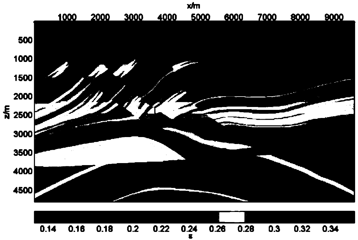
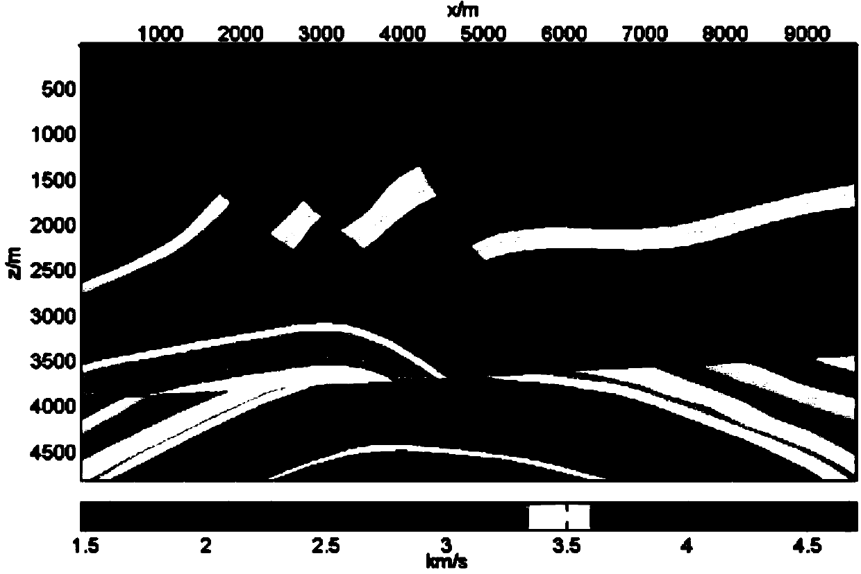
[0249] refer to Figure 10(a) to Figure 10(f) Shown are the schematic diagrams of Poynting vectors of elastic waves before and after the separation of longitudinal and transverse waves and the decomposition of directional waves in the x component and z component. refer to Figure 10(a) to Figure 10(c) As shown, Fig. 10(a) is a schematic diagram of the Poynting vector of the elastic wave in the x-component, and Fig. 10(b) and Fig. 10(c) are the Poynting vectors after the separation of the longitudinal and shear waves and the separation of the shear waves in the x direction It can be seen that the Poynting vector is well separated, and its amplitude and phase are well maintained. Figure 10(d) to Figure 10(f) The schematic diagrams of the Poynting vectors of the longitudinal waves after the separation of the longitudinal waves and the shear waves in the z direction are similar to those in Figure 10(d) to Figure 10(f), and will not be repeated here.

Embodiment 2

[0251] refer to Figure 11(a) to Figure 11(g) As shown, the present embodiment uses the point impulse wave response to verify the technical solution of the present application. It can be seen that Fig. 11(a) is the Poynting vector of the wave, and Fig. 11(b) and Fig. 11(c) are the The Poynting vector after longitudinal and transverse wave-ground separation, and Figure 11(d) to Figure 11(g) It is the Poynting vector calculated after separating the vertical and horizontal waves on the basis of separating the vertical and horizontal waves. Then, the Poynting vectors of the wave fields in all directions are calculated on this basis; then, the Poynting vectors are used to output the reflection angles of the wave fields, and then the corresponding ADCIGs gathers are generated. This method avoids the influence of wave front overlap and wave mode coupling on the calculation of wave propagation direction, and the generated ADCIGs gathers are more accurate and the imaging effect is be...


PUM


Abstract

The invention discloses a method and an apparatus for determining a poynting vector of a seismic wave field and a computer storage medium. The method comprises the following steps: establishing an underground shot point forward-propagation wave field and a detection point back-propagation wave field; determining a medium type of the forward-propagation wave field and the back-propagation wave field; when the media are isotropic media, performing vertical-horizontal wave field separation on the forward-propagation wave field and the back-propagation wave field according to a preset equation decoupling algorithm, and when the media are heterogeneous anisotropic media, performing longitudinal-horizontal wave field separation on the forward-propagation wave field and / or back-propagation wave field according to a preset variation function IDW interpolation algorithm; decomposing a separated longitudinal-wave wave field and / or a transverse-wave wave field in a top direction, a bottom direction, a left direction and a right direction, and obtaining multiple directional-wave wave fields; and selecting multiple directional-wave wave fields from the multiple directional-wave wave fields, and calculating the poynting vector of the multiple directional-wave wave fields. By adopting the method, the poynting vector of each decomposed directional wave field can be calculated, so that more accurate angle-domain imaging gather can be obtained, and the imaging quality can be improved.

Description

technical field [0001] The present application relates to the field of seismic exploration, in particular to a method, device and computer storage medium for determining a Poynting vector of a seismic wave field. Background technique [0002] Poynting (Poynting) vector is the energy flow density vector. Among them, the Poynting vector is used to represent the electromagnetic field energy passing through the unit surface perpendicular to the vector direction per unit time. Its vector value is the cross product of the electric field strength and the magnetic field strength, and the azimuth represents the propagation direction of the electromagnetic wave. [0003] Yoon and Marfurt (2003) introduced the Poynting vector into the field of seismic exploration, gave the calculation formula of the Poynting vector in the seismic wave field, and used the Poynting vector of the shot point wave field and the Poynting vector of the receiver point wave field Ting vector outputs the refle...

Claims


Application Information

Patent Timeline
Patent Type & Authority Patents(China)
IPC IPC(8): G01V1/28
CPCG01V1/28
Inventor 王之洋胡婷袁雨欣刘洪
Owner INST OF GEOLOGY & GEOPHYSICS CHINESE ACAD OF SCI
Why Eureka
Try Eureka