Test method of influence of heat effect on transformer anti-short circuit capability
A technology of short-circuit resistance and short-circuit test, which is applied in transformer testing, instrumentation, and measurement of electrical variables, etc., and can solve problems such as inaccurate maximum short-circuit current
Active Publication Date: 2017-09-08
YUNNAN POWER GRID CO LTD ELECTRIC POWER RES INST
View PDF7 Cites 2 Cited by
- Summary
- Abstract
- Description
- Claims
- Application Information
AI Technical Summary
Problems solved by technology
[0004] However, due to the certain load of the transformer in the actual operation process, the transformer winding has a thermal effect. When the transformer heats up, its short-circuit resistance capability will change. The above short-circuit test is carried out without considering the thermal effect of the transformer, resulting in The maximum short-circuit current is inaccurate
Method used
View moreImage
Smart ImageViewing Examples
Examples
specific Embodiment approach
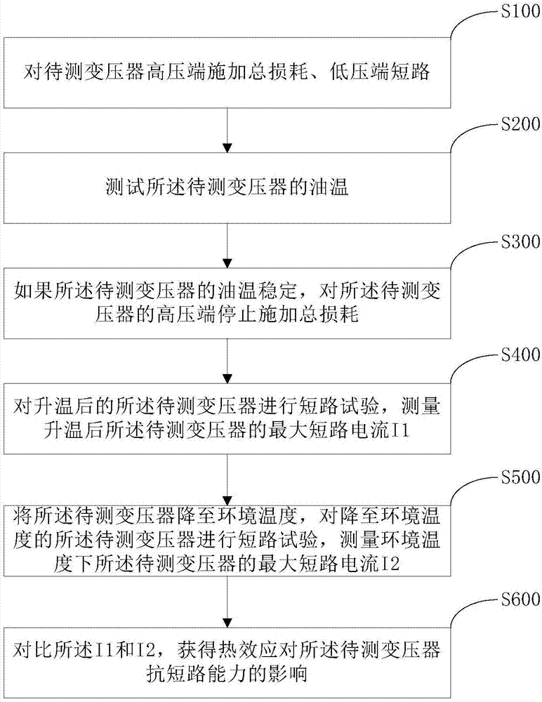
[0054] In a possible implementation manner, the specific implementation manner of step S400 includes:
Login to View More PUM
 Abstract
The present invention discloses a test method of influence of heat effect on a transformer anti-short circuit capability. The method comprises: applying total loss and a low-voltage end short circuit to the high-voltage end of a transformer to be tested, wherein the total loss is the sum of the no-load loss and the load loss of the transformer to be tested; testing the oil temperature of the transformer to be tested; if the oil temperature of the transformer to be tested is stable, stopping applying the total loss to the high-voltage end of the transformer to be tested; performing short-circuit test of the transformer to be tested after temperature rising, and measuring the maximum short-circuit current I1 of the transformer to be tested after temperature rising; decreasing the transformer to be tested to environment temperature, performing short-circuit test of the transformer to be tested which is reduced to the environment temperature, and measuring the maximum short-circuit current I2 of the transformer to be tested in the environment temperature; and comparing the I1 with the I2, and obtaining the influence of the heat effect on the anti-short circuit capability of the transformer to be tested. The test method is suitable for arbitrary types of transformers, is accurate in test result, simple and easy to operate.
Description
technical field [0001] The invention relates to the technical field of transformer short-circuit test, in particular to a test method for the influence of thermal effect on transformer short-circuit resistance capability. Background technique [0002] Transformer is one of the most important equipment in power system. Its operating condition not only affects its own safety, but also affects the stability and reliability of the entire power system. The power grid is often short-circuited due to lightning strikes, relay protection malfunction or refusal to operate, and the strong impact of short-circuit current may damage the transformer. Therefore, it is necessary to study the short-circuit resistance of the transformer through short-circuit tests. [0003] The current transformer short-circuit test is to directly apply a certain voltage to the transformer according to the GB1094.5-2008 standard, and measure the maximum short-circuit current of the transformer. The greater th...
Claims
Login to View More Application Information
Patent Timeline
 IPC IPC(8): G01R31/02G01R31/00
CPCG01R31/003G01R31/50G01R31/62
Inventor 邹德旭钱国超颜冰王山刘光祺井永腾
Owner YUNNAN POWER GRID CO LTD ELECTRIC POWER RES INST
Features
- R&D
- Intellectual Property
- Life Sciences
- Materials
- Tech Scout
- Unparalleled Data Quality
- Higher Quality Content
- 60% Fewer Hallucinations
Learn More Browse by: Latest US Patents, China's latest patents, Technical Efficacy Thesaurus, Application Domain, Technology Topic, Popular Technical Reports.
© 2025 PatSnap. All rights reserved.Legal|Privacy policy|Modern Slavery Act Transparency Statement|Sitemap|About US| Contact US: help@patsnap.com


