
Patsnap Eureka
For R&D, Patsnap Eureka makes reading and utilizing patents & technical documents easy.
Patsnap Eureka AIR
Designed for self-driven R&D workflows. Generate viable solutions, solve complex R&D challenges, empower your innovation with AI.

Patsnap Eureka Materials
Designed for material experts only. Revolutionize your material R&D, from search, analyze, to developing new materials.

TechResearch
Generate reliable direction feasibility study reports for your R&D in just a few steps.

TechSeek
Discover and master advanced knowledge NOW. Basics, ideas, possibilities, all at once.

TechMind
As an expert in R&D Theories, TechMind can generates customized viable solutions instantly.

TechRisk
Analyze your overall solution with one click, know your potential R&D risks in advance.

TechMonitor
Get weekly tech updates, stay abreast of the latest tech innovations and key insights.
Industrial VOCs waste gas treatment method and treatment system
A waste gas treatment and waste gas technology, which is applied in the field of industrial VOCs waste gas treatment methods and treatment systems, can solve the problems of complex device structure and high cost, and achieve the effect of low cost and simple structure
- Summary
- Abstract
- Description
- Claims
- Application Information
AI Technical Summary
Problems solved by technology
Method used
Image

Examples
Embodiment approach
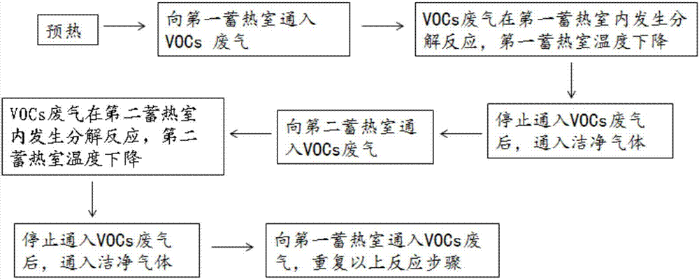
[0047] As a preferred embodiment of the present invention, the processing method includes the following steps:
[0048] Step a): preheating the first regenerator and the second regenerator of the regenerative thermal oxidation furnace;
[0049] Step b): After the preheating is completed, the VOCs waste gas is first passed into the first regenerator, and the VOCs waste gas undergoes a decomposition reaction in the first regenerator and the combustion chamber, and the decomposed gas flows through the second regenerator. After the regenerator, it is discharged out of the regenerative thermal oxidation furnace;
[0050] Step c): When the temperature of the first heat storage chamber drops to 500-760°C, stop the introduction of VOCs exhaust gas, and pass clean gas into the first heat storage chamber, so that the residual gas in the first heat storage chamber The VOCs waste gas in the heat chamber continues to flow and heat up, and flows through the second heat storage chamber afte...
Embodiment 1
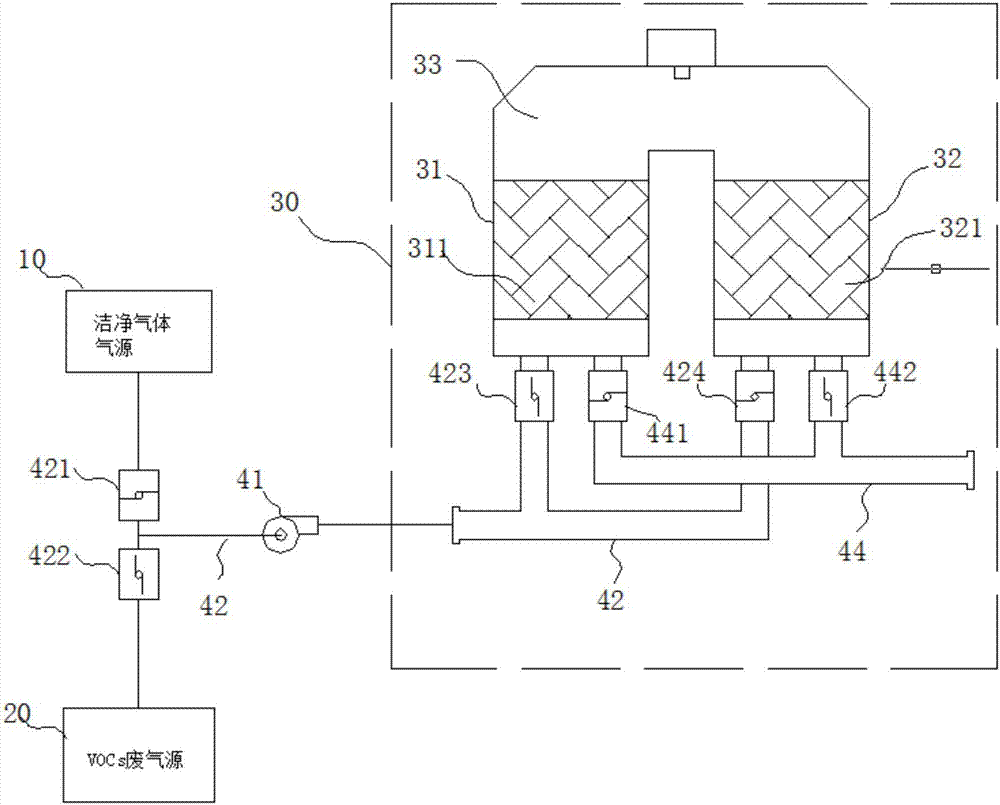
[0073] Such as figure 1 As shown, this implementation is an industrial VOCs waste gas treatment system, the treatment system includes a regenerative thermal oxidation furnace 30, and the regenerative thermal oxidation furnace 30 is connected to the VOCs waste gas source 20 and the clean gas source 10 respectively through the air inlet system Pass; VOCs waste gas source 20 and clean gas source 10 are supplied to the regenerative thermal oxidation furnace 30 alternately through the air intake system. Wherein, the regenerative thermal oxidation furnace 30 includes a first regenerator 31, a second regenerator 32, and a combustion chamber 33 located between the first regenerator 31 and the second regenerator 32; the first regenerator 31 The second regenerator 32 is respectively connected to the VOCs waste gas source 20 and the clean gas source 10 through the air intake system; The chamber 31 or the second regenerator chamber 32 is supplied with air.
[0074] The air intake system...
Embodiment 2
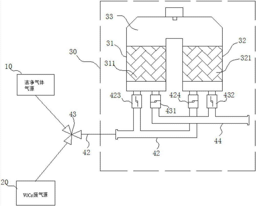
[0088] Such as figure 2 As shown, this implementation is an industrial VOCs waste gas treatment system. The difference between this embodiment and Embodiment 1 lies in the setting of the air intake system.
[0089] In this embodiment, the air inlet system includes an air inlet pipe 42, and a three-way valve 43 is provided on the air inlet pipe 42. The three-way valve 43 includes two air inlets and one air outlet, and the two air inlets are connected to the clean gas source 10 respectively. And the VOCs exhaust gas source 20, the air outlet communicates with the regenerative thermal oxidation furnace 30 through the air inlet pipe 42.
PUM
 Abstract
Description
Claims
Application Information
 - R&D Engineer
- R&D Manager
- IP Professional
- Industry Leading Data Capabilities
- Powerful AI technology
- Patent DNA Extraction
Browse by: Latest US Patents, China's latest patents, Technical Efficacy Thesaurus, Application Domain, Technology Topic, Popular Technical Reports.
© 2024 PatSnap. All rights reserved.Legal|Privacy policy|Modern Slavery Act Transparency Statement|Sitemap|About US| Contact US: help@patsnap.com