Control Method of Residuals in Machining Process of Cavity with Annular Gap

A technology of annular gap and processing process, which is applied in the field of excess material control in the processing of the pintle injector shell of the thrust chamber of the liquid rocket engine, can solve problems such as difficult to remove and clean, launch mission failure, and easy entry of chips, etc., to achieve The cleanliness of the inner cavity of the product is satisfactory, it is convenient to fill and clean, and the effect of breaking the seal

Active Publication Date: 2019-03-15
XIAN SPACE ENGINE CO LTD
View PDF5 Cites 1 Cited by
  • Summary
  • Abstract
  • Description
  • Claims
  • Application Information

AI Technical Summary

Problems solved by technology

The injector shell processing process is long, covering shell blank processing, shell semi-finished welding and shell precision machining. Affect the performance of the product, in severe cases, it will lead to a decrease in engine performance, or even failure of the launch mission
[0003] In the conventional processing process, the entrance of the annular gap is often blocked by sticking insulating tape to prevent excess material from entering the inner cavity of the product. The effect of cutting temperature and cutting temperature makes the tape easy to fall off, causing cutting fluid, chips, etc. to enter the annular gap of the product and produce excess; the excess that enters the annular gap is difficult to remove and clean with conventional cleaning methods, bringing safety to the use of the product Hidden danger

Method used


Image

  • Control Method of Residuals in Machining Process of Cavity with Annular Gap

Examples


specific Embodiment approach

[0029] The specific embodiment of the present invention comprises the following steps:

[0030] (1) Put the clean solid lard in a drying box with a temperature of 50-60°C and melt it into a liquid state; then use a 400-mesh filter to filter the lard to ensure that there is no excess in the lard;

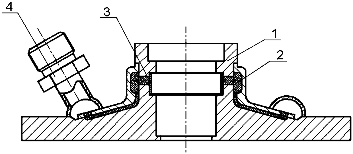
[0031] (2) block the nozzle 4 with a protective piece, put the product 1 upside down in an iron basin container filled with lard, so that the lard can be immersed in the bottom part of the annular gap cavity;

[0032] (3) Place the container and the product together in the refrigerator for 4 hours to freeze the lard completely into a solid state and ensure that the lard is completely filled in the annular gap; clean up;

[0033] (4) According to the width of the annular groove of the product 3.5mm and the diameter of 31mm, considering the overlap after bending, the length of the required spring steel sheet is calculated to be 100mm, and then the spring steel sheet is pre-bent into a...


PUM

PropertyMeasurementUnit
lengthaaaaaaaaaa

Abstract

The invention provides a method for controlling excess objects in cavities with annular gaps during a machining process. The method is as follows: before machining the molded surface of a cavity, adopting clean animal fat as an annular gap filler, and using a spring steel sheet to block an annular gap inlet, so as to prevent large cuttings, fine cuttings and cutting fluid from entering the product cavity; after machining, adopting heat treatment, hot steam blowing, ultrasonic cleaning and under-pressure cleaning processes to clean the lard in the cavity annular gap, so as to ensure that the cleanliness of the product cavity meets requirements. According to the invention, the technical problem of excess objects prevention and control during the machining process of the shell of a pintle-type injector in the thrust chamber of a liquid-propellant rocket engine is effectively solved, thereby avoiding the impact of the excess objects on the product performance and improving the operational reliability of the product.

Description

technical field [0001] The invention belongs to the technical field of liquid rocket engine manufacturing, and mainly relates to a method for controlling redundant matter in the processing of a pintle type injector shell in a thrust chamber of a liquid rocket engine. Background technique [0002] Due to its simple structure, low cost, and excellent performance, the pintle thrust chamber has obvious advantages in the field of variable thrust engines and low-cost booster engines. Due to the integrated design of the pintle injector, the difficulty of processing the shell of its important parts and the difficulty of excess control are greatly increased. The injector shell processing process is long, covering shell blank processing, shell semi-finished welding and shell precision machining. It will affect the performance of the product, and in severe cases, it will lead to a decrease in engine performance, or even failure of the launch mission. [0003] In the conventional proc...

Claims


Application Information

Patent Timeline
Patent Type & Authority Patents(China)
IPC IPC(8): B08B5/02B08B3/08B08B3/12B08B1/00B08B3/02B08B13/00G01N15/02
CPCB08B1/002B08B3/02B08B3/08B08B3/12B08B5/02B08B13/00G01N15/02
Inventor 李波仵亮赵飞赵保科李旭光张鹏梁相鹏
Owner XIAN SPACE ENGINE CO LTD
Why Eureka
Try Eureka