
Photosensitive vibration device

A vibration device, photosensitive technology, applied in the field of virtual reality

Inactive Publication Date: 2017-09-08
黄宁
View PDF14 Cites 0 Cited by
  • Summary
  • Abstract
  • Description
  • Claims
  • Application Information

AI Technical Summary

Problems solved by technology

[0003] However, there are big problems with the authenticity of real-virtual, so a more realistic device is needed to improve

Method used


Image

  • Photosensitive vibration device
  • Photosensitive vibration device
  • Photosensitive vibration device

Examples


Embodiment Construction

[0013] The following are specific embodiments of the present invention, further describing the technical solutions of the present invention, but the present invention is not limited to these examples.

[0014] Put the photosensitive vibration device in the toy laser gun, make the toy laser gun generate two laser beams, and the light energy generated by one laser makes the photosensitive vibration device vibrate, and drives the toy laser gun to produce a feeling similar to recoil, which is more realistic to use. One end of the laser can still shoot through the muzzle.

[0015] Put the photosensitive vibration device on the light-transmitting sleeve, gather and adsorb on the large-scale heterosexual magnetic field, and wrap the heterosexual magnetic field according to the shape distribution of the heterosexual magnetic field to form a game scene. The mutual vibration repulsion of the photosensitive vibration devices produces smoke and dust effects, making the form more beautiful....


PUM


Abstract

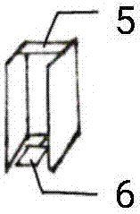
A photosensitive vibration device is characterized by comprising a light-transmitting sleeve and a vibration device, wherein the photosensitive vibration device has a photosensitive shell, a continuous spring device and a magnet block; the photosensitive shell of the photosensitive vibration device is formed by photosensitive resistance; a vibration hole is connected with a spring sleeve of the continuous spring device; the continuous spring device has the spring sleeve, a spring and a gear; and the gear is only provided with one gear tooth and the gear tooth is a long gear tooth.

Description

technical field [0001] The invention belongs to the field of virtual reality, in particular to a small structure. Background technique [0002] With the rapid development of virtual reality, the virtual world is becoming more and more perfect, and people's virtual life is more abundant. Especially the development of real virtual experience has alleviated people's sense of emptiness in real life. [0003] But there is a big problem with the real-virtual authenticity, so a more real device is needed to perfect it. Contents of the invention [0004] The object of the present invention is to provide a photosensitive vibration device with simple structure to solve the above problems in the prior art. [0005] The purpose of the present invention can be achieved through the following technical solutions: a photosensitive vibrating device, characterized in that it comprises a light-transmitting sleeve and a photosensitive vibrating device, the said light-transmitting sleeve is ...

Claims


Application Information

Patent Timeline
Patent Type & Authority Applications(China)
IPC IPC(8): A63H33/18A63H33/22
CPCA63H33/18A63H33/22
Inventor 黄宁
Owner 黄宁
Learn More