
Method for improving adaptive variable gain fast response phase-locked loop

A fast-response, phase-locked loop technology, applied in the direction of automatic power control, electrical components, etc., can solve the problems of small bandwidth, slow dynamic response speed, increase of transition time of the phase-locked loop system, etc., to reduce nonlinearity, The effect of improving dynamic response speed and increasing bandwidth

Active Publication Date: 2017-09-05
江苏广识电气有限公司 +1
View PDF8 Cites 6 Cited by
  • Summary
  • Abstract
  • Description
  • Claims
  • Application Information

AI Technical Summary

Problems solved by technology

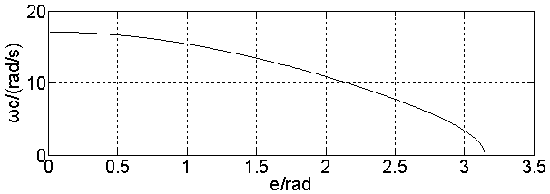
However, when the external input signal is a large signal, the angle of deviation e larger, sin e Can not be ignored, the sin at this time e The degree of nonlinearity is large, and the cutoff frequency ω c Decrease, the actual value of the bandwidth is smaller than the theoretical value, the transition time of the phase-locked loop system increases, and the corresponding dynamic response speed becomes slower

Method used


Image

  • Method for improving adaptive variable gain fast response phase-locked loop
  • Method for improving adaptive variable gain fast response phase-locked loop
  • Method for improving adaptive variable gain fast response phase-locked loop

Examples


Embodiment Construction

[0042] In order to make the experimental purpose and advantages of the present invention clearer, the following structural drawings illustrate further detailed explanations: figure 1 Is the structure diagram of the phase-locked loop, the first is the three-phase voltage u a , u b , u c Converted by Clarke transform to u α , u β , and then use the Park transform to convert u α , u β converted to u d , u q

[0043]

[0044]

[0045] 1, is the output angle feedback of the phase-locked loop, θ is the phase A grid voltage angle, is the angular deviation; ,in is the voltage vector magnitude in the synchronous coordinate system.

[0046] In the nonlinear mathematical model, the phase identification link uses

[0047] way, so there is a nonlinear part in the system model: , which exists in the system forward pass. According to the nonlinear model of the phase-locked loop, the open-loop transfer function of the system is obtained, and the formula...


PUM


Abstract

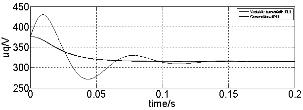
The invention discloses a method for improving a phase-locked loop based on an adaptive variable gain for realizing fast response. The method comprises the following steps: sampling a grid three-phase voltage signal, and converting a three-phase voltage into a two-phase voltage (the formula is as shown in the specification) through Clark transform and Park transform; obtaining an open-loop transfer function of the phase-locked loop containing a nonlinear phase discrimination link according to a phase-locked loop (SRF-PLL) nonlinear mathematic model based on a synchronous coordinate system; obtaining the relationship between open loop cut-off frequency (the formula is as shown in the specification) and an input deviation (the formula is as shown in the specification) through the transfer function, and constructing a variable gain function containing an amplitude (the formula is as shown in the specification), a nonlinear system deviation (the formula is as shown in the specification) and linear system deviation (the formula is as shown in the specification) to reduce the nonlinearity of the system; reforming the traditional PI controller through the variable gain function, and designing an adaptive integral gain (the formula is as shown in the specification) to replace the original (the formula is as shown in the specification) so as to obtain an adaptive variable gain phase-locked loop system; and performing time domain analysis on a closed loop equivalent linear system to accomplish the integration of system parameters. According to the method disclosed by the invention, the variable gain control is constructed to reduce the degree of nonlinearity of the open-loop system, reduce the coupling relationship between the angular velocity and the angle, shorten the dynamic transition time of the phase-locked loop and performs dynamic response contrastive analysis on the traditional phase-locked loop system and the improved phase-locked loop system by using a simulation platform.

Description

technical field [0001] The invention relates to an improved method of a phase-locked loop with adaptive variable gain, which is used to realize fast response of the system. Background technique [0002] With the rapid development of power electronics technology, the role of phase-locked loops is becoming more and more important. The feature of the phase-locked loop is to use the external input reference signal to control the frequency and phase of the internal oscillation signal of the loop, so as to achieve the purpose of synchronizing the external input signal of the electronic device with the internal oscillation signal. This technology is very useful in the data acquisition system, because through the phase-locked loop, different data acquisition boards can share the same sampling clock, so the sampling clock is also synchronized, and the accuracy is greatly improved. On the other hand, the phase detection link of the phase-locked loop uses way to achieve, when the ex...

Claims


Application Information

Patent Timeline
Patent Type & Authority Applications(China)
IPC IPC(8): H03L7/107
CPCH03L7/107
Inventor 孟献仪袁朋生张洋经雪园王青松刘雷赵晓波胡海涛
Owner 江苏广识电气有限公司
Learn More