Diesel engine fuel oil injection micro electric control unit combined pump

A diesel engine and fuel injection technology, which is applied in fuel injection pumps, engine control, fuel injection control, etc., can solve the problems of complex single pump structure, large shape that cannot be installed, and poor uniformity control, so as to improve the consistency of fuel volume The effects of stability and uniformity, precise fuel injection timing, and strong idling loading capacity

Pending Publication Date: 2017-09-05
NANYUE FUEL INJECTION SYST CO LTD
View PDF6 Cites 1 Cited by
  • Summary
  • Abstract
  • Description
  • Claims
  • Application Information

AI Technical Summary

Problems solved by technology

[0004] The technical problem to be solved by the present invention is to meet the non-road China's third stage, fourth stage and above emission standards, while reducing the fuel consumption of non-road machinery, the fuel injection system overcomes the low pressure at the pump end of the existing distribution pump fuel injection pump, and the response speed Slow speed, poor uniformity control and existing unit pump complex structure, large shape can not be installed, and provide a diesel engine micro fuel injection electronic control unit combination pump controlled by an electronic control unit (ECU), the diesel engine The pump end pressure of the fuel injection electronically controlled unit combination pump reaches above 1200bar, and the nozzle end pressure reaches above 1400bar, with high control precision, flexible control, small shape, and optimal fuel injection quantity and injection timing under various working conditions

Method used


Image

  • Diesel engine fuel oil injection micro electric control unit combined pump
  • Diesel engine fuel oil injection micro electric control unit combined pump
  • Diesel engine fuel oil injection micro electric control unit combined pump

Examples


Embodiment Construction

[0030] In order to make the technical means, creative features, objectives and effects achieved by the present invention easy to understand, the present invention will be further described below in conjunction with specific illustrations.

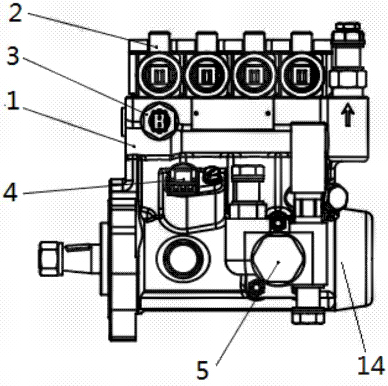
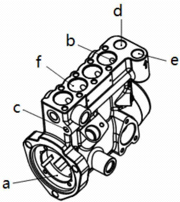
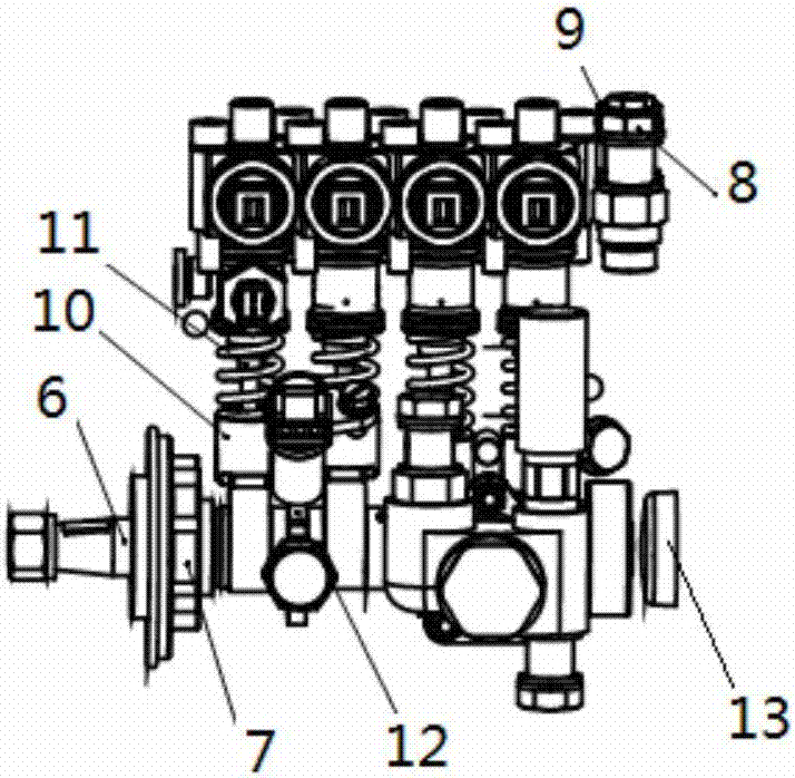
[0031] figure 1 , figure 2 with image 3 See shown. The four-cylinder diesel engine fuel injection electronic control unit combination pump shown in the figure includes a pump body 1, and the pump body 1 is connected to the engine (not shown in the figure) by means of a mechanical connection such as a flange or a bracket.

[0032] The pump body 1 of the diesel engine fuel injection electronic control unit combination pump is provided with a camshaft installation chamber a below and four cylinder chambers f above, and the distance between the cylinder centers between adjacent cylinder chambers is ≤33mm. Height≤160mm. The bottom of the four cylinder chambers f communicates with the camshaft installation chamber a. An oil passage d and a...


PUM


Abstract

The invention discloses a diesel engine fuel oil injection micro electric control unit combined pump. The diesel engine fuel oil injection micro electric control unit combined pump comprises a pump body, a cam shaft, an oil conveying pump assembly, a plurality of electric control unit pump bodies, a phase sensor signal generation wheel, a phase sensor, a fuel oil temperature sensor, a time correcting positioning device signal generation wheel and a time correcting positioning device. The cam shaft is mounted in the pump body; the oil conveying pump assembly is mounted on the lower portion of one side outside the pump body; the multiple electric control unit pump bodies are mounted in a plurality of cylinder chambers on the pump body side by side. The phase sensor signal generation wheel is mounted on the cam shaft and rotates synchronously with the cam shaft. The phase sensor is arranged on the pump body and used for detecting a signal generated by a signal generation part on the phase sensor signal generation wheel. The fuel oil temperature sensor is arranged on the pump body and used for detecting the temperature of fuel oil in a high pressure oil duct. The time correcting positioning device signal generation wheel is arranged on the cam shaft and rotates synchronously with the cam shaft. The time correcting positioning device is arranged on the pump body and used for detecting a signal generated by the time correcting positioning device signal generation wheel. The time correcting positioning device is controlled by an ECU to control the cam shaft to be in a correct oil supplying position so as to meet the set oil injection law.

Description

technical field [0001] The invention relates to the technical field of diesel engine fuel injection, in particular to a diesel engine fuel injection micro electronic control unit combination pump. Background technique [0002] The low-power engine has a small shape and a small installation space. The existing low-power engine fuel injection system is matched with a distribution pump, which is invented to improve the emission level and reliability level of the low-power engine. [0003] Chinese invention patent CN201010261721.X discloses a diesel engine fuel injection electronically controlled unit combined pump, including a pump body; a camshaft installed in the pump body; an oil delivery pump assembly driven by the camshaft installed on one side of the pump body, The fuel delivery pump assembly pumps fuel into the high-pressure oil passage in the pump body; it also includes several sets of electronically controlled unit pumps installed in parallel on the pump body, and the ...

Claims


Application Information

Patent Timeline
IPC IPC(8): F02M59/10F02D41/38F02D41/40
CPCF02D41/009F02D41/38F02D41/401F02D41/406F02M59/102F02D2041/389F02D2200/0606
Inventor 邓飞龙美彪欧阳玲湘黄民备邓秋明李少鹤陈颍
Owner NANYUE FUEL INJECTION SYST CO LTD
Why Eureka
Try Eureka